Install in junction box, Echo™ light sensor, N o t e – ETC Echo Light Sensor User Manual
Page 4
E T C I n s t a l l a t i o n G u i d e
Echo™ Light Sensor
Echo Light Sensor Installation Guide Page 4 of 12
Install in Junction Box
Step 1: Pull Belden 8471 (or equivalent) and 14 AWG (2.5mm
2
) ground wire to
the junction box.
Step 2: If you are installing the controller in series (continuing the data run)
to other sensors, sensor controllers, or stations, use the provided
EchoConnect pigtail and ESD ground pigtail to make the terminations.
If you are not continuing the data run, the pigtails are not required,
proceed to Step 3.
a: Strip each wire to the appropriate length, depending on the wire nut
or other termination used (wire nuts are not provided).
b: Twist the data - (typically black) EchoConnect wire, the black lead
from the EchoConnect pigtail, and any continuing EchoConnect
(typically black) wire together and secure with the wire nut.
c: Repeat the above steps for the data + (typically white)
EchoConnect wires, and for the ESD ground wires.
Step 3: If you are installing the Primary and/or Optional (second) Light
Sensor Head remotely from the controller, reference
Light Sensor Heads Remotely (optional) on page 7
, then return to
these instructions. If you are not remoting a Light Sensor Head,
proceed to Step 4.
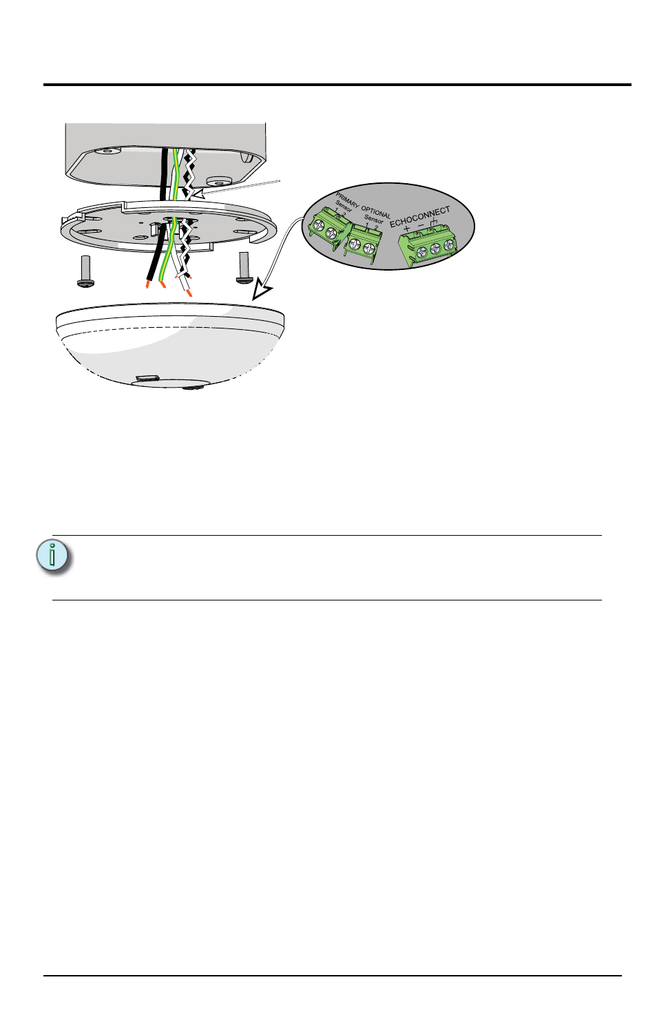
N o t e :
Primary Sensor and Optional Sensor wires should terminate
directly to the terminals located on the controller.
the Light Sensor Heads Remotely (optional)” on page 7.
Terminate
wires here
Optional
sensor wires
Termination is available at the Controller for the
EchoConnect communication bus and up to two
Light Sensor Heads. Flexibility is provided with regards
to how the Light Sensor Head(s) is installed. You can
install a Light Sensor Head at the controller, or you can
install up to two Light Sensor Heads remotely.