External resistor, Latch mode (lm), “30/60” hall sensor selector (sel) – ElmoMC SimplIQ Analog Servo Amplifiers-Piccolo Installation User Manual
Page 26: Amplifier enable logic
Piccolo Installation Guide
Servo Control Operation
MAN-PICIG (Ver. 2.301)
26
4.5.2.
External Resistor
Connect an external resistor between terminal J2/3 (ECLP) and terminal J2/2 (ECLRET). The
resistor value is given by::
(Kohm) = 37.4 *
R
ECLP
Ip(new)
Ip(nom)
- 1
(Kohm) = 37.4 *
R
ECLP
(Kohm) = 37.4 *
R
ECLP
Ip(new)
Ip(nom)
- 1
•
0 < R
ECLP
< 36.4 K (1/8 Watt)
•
At R
ECLP
greater than 36.4 K, the current limit will be internally clamped to the nominal
value.
•
I
P(nom)
is the nominal peak current limit of the amplifier.
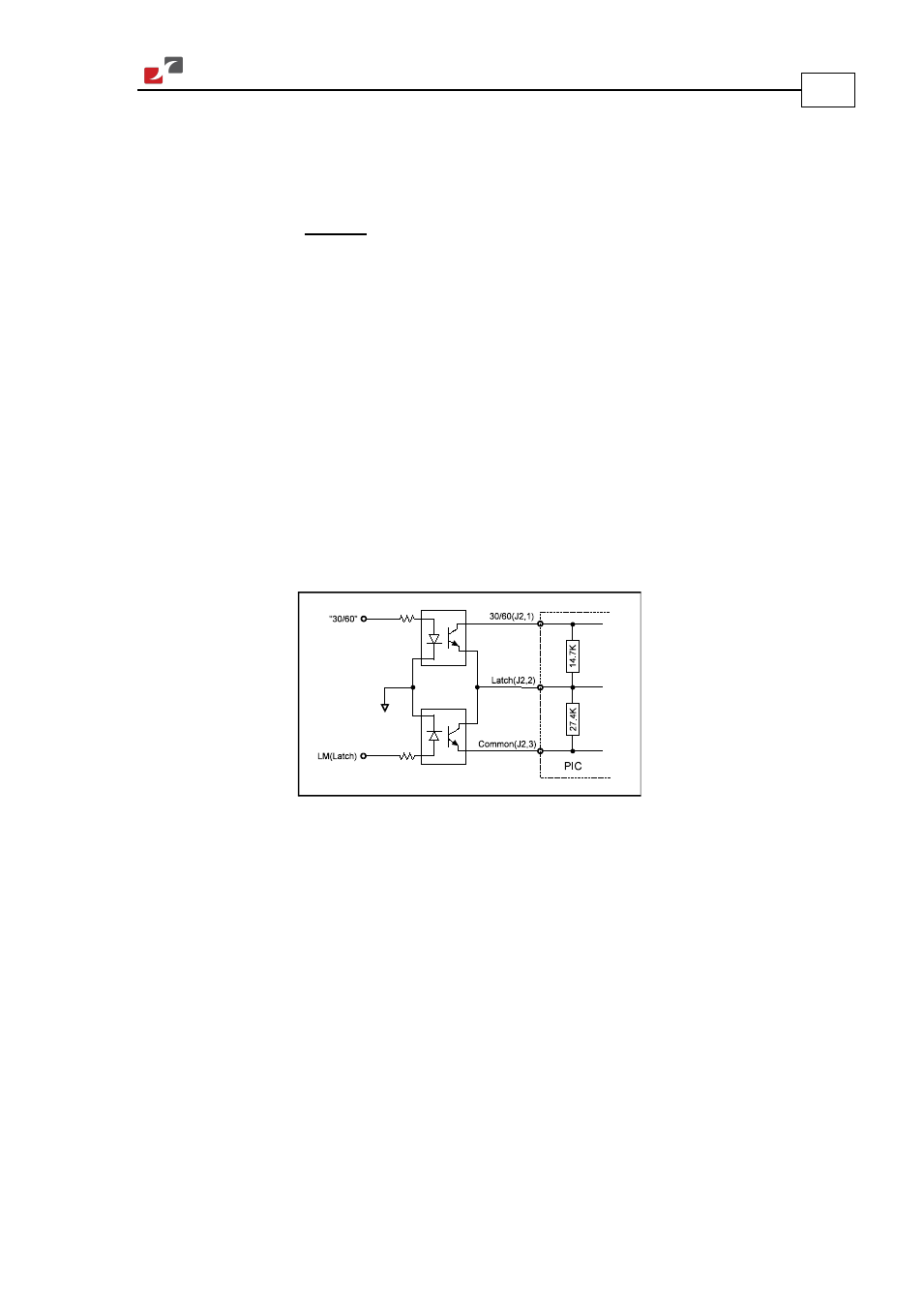
4.6. Latch Mode (LM)
By connecting J2/2 to J2/3, the amplifier can be latched to Disable mode whenever a Short,
Commutation or Over Temperature failure occurs. Disabling the amplifier temporarily (by
removing the power from Enable pins J2/4 and J2/6) resets the latch. Be sure to restore the
Enable connection when the reason for the event no longer exists. For permanent selection, a
simple short is recommended. For remote selection, use the following scheme.
Figure 6: “30/60” and LM Remote Control
4.7. “30/60” Hall Sensor Selector (SEL)
This is the input for selecting the Hall signal format. The default (pin J2/1 open) is 60°. Shorting
pin J2/1 to pin J2/2 (LM) changes the selected Hall format to 30°. For permanent selection, use
a simple short; for remote selection, use the scheme shown in Figure 6.
4.8. Amplifier Enable Logic
Pins J2/4 and J2/6 are the inputs of an opto-coupler, which must be energized to enable
operation of the amplifier. If the Enable input is kept high before turning on the amplifier, the
amplifier power output will be active immediately upon power on.