Step 7. operational settings – Elkhart Brass Sidewinder EXM Quick Install Guide User Manual
Page 3
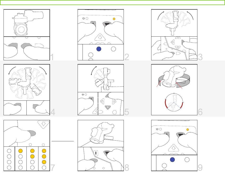
CALIBRATE HORIZONTAL
ENTER SETUP MODE
CALIBRATE VALVE
On the Handheld
controller, press
and hold FOG &
STREAM buttons
for 5 seconds.
Blue Status LED
on monitor &
yellow LED on
controller will be
lit.
On the Joystick
controller, press
and hold AUX &
PRESET until LEDs
turn on.
You will need to
calibrate the
valve before use.
While you are
NOT in setup
mode, place the
valve in a half
open position,
then press and
hold PRESET &
CLOSE until
calibration
begins. The valve
will automatically
start to calibrate
itself.
Aim monitor at
center forward
“zero” position.
Hold PRESET, then
press and release
LEFT or RIGHT.
The Status LED on
monitor should
blink and return to
solid. Release
PRESET button.
KEEP-OUT ZONES
VERTICAL TRAVEL LIMITS
HORIZONTAL TRAVEL LIMITS
Upper:
Move monitor to
highest point of
travel. Hold
STREAM, then
press UP, and
release both.
Lower:
Move monitor to
lowest point of
travel. Hold
STREAM, then
press DOWN,
and release both.
Move monitor to
the left limit and
press CLOSE.
Move monitor to
the right limit and
press OPEN.
Maximum travel
limits will allow
+175° from the
calibrated “zero”
position in either
direction.
Lower Left:
Move to top right
corner of the lower
left zone, hold
PRESET, press
CLOSE, and
release both.
Lower Right:
Move to top left
corner of the lower
right zone, hold
PRESET, press
OPEN, and
release both.
EXIT SETUP MODE
STOW POSITION
MONITOR MOTOR SPEEDS
Move monitor to
desired position,
then press FOG
and OSC at the
same time to
store a stow
position.
Stow position
must be within
allowed limits of
travel.
Pressing the OSC
button will cycle
through the
monitor speed
options:
LEDs - Vert / Horz
0 - Fast / Fast
1 - Slow / Fast
2 - Fast / Slow
3 - Slow / Slow
Press and release
FOG & STREAM
simultaneously
one time. LEDs will
turn off.
Press and release
AUX & PRESET
simultaneously
one time if using
the Joystick
controller.
Step 7. Operational Settings
NOTE: (R) This step is required. (O) This step is optional.
OSC
OPEN
PRESET
CLOSE
(R)
(R)
R
L
Lower Left Zone:
Top right corner
Lower Right Zone:
Top left corner
0°
Right Travel Limit
*Monitor in drawing may differ from actual monitor
Left Travel Limit
Lower Left
Zone
Lower Right
Zone
(O)
(O)
(O)
(O)
0
1
2
3
(O)
STATUS
POWER
STREAM
STATUS
POWER
STREAM
PRESET
OPEN
AUX
OSC
OPEN
CLOSE
OSC
FOG
STREAM
135°
max.
travel
STREAM
AUX
OSC
L
U