Step 4. rf installation, Step 5. component mounting step 6. wiring, Drill mount holes can network wiring diagram – Elkhart Brass Sidewinder EXM Quick Install Guide User Manual
Page 2: Drill can holes, Mount components, Supply power - fuse
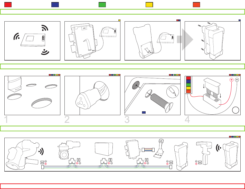
Step 4. RF Installation
Panel Mount Controller
Handheld Controller /
Docking Station
Joystick Controller
OEM Interface Module
Position Feedback Display
INSTALL RF MODULE
INSTALL RF - OEM
INSTALL RF - HANDHELD
INSTALL BATTERY PACK
Step 5. Component Mounting
Step 6. Wiring
Use mounting templates found in the
instruction manual for dimensions.
DRILL MOUNT HOLES
CAN NETWORK WIRING DIAGRAM
Drill holes for CAN network and power
cables for each component.
DRILL CAN HOLES
Mount components using 10-24 x 1/2”
screws. Use Loctite 242 or equivalent.
MOUNT COMPONENTS
Install a 1A fuse (12VDC) into the positive
power lead; 0.5A fuse for 24VDC.
SUPPLY POWER - FUSE
Connect entire CAN network together using 18-22 AWG. Ensure every component connected to the CAN network is connected in between
the two (2) end components that have CAN termination. Please refer to the BLUE, GREEN, and BLACK lines as the CAN wires below.
Before continuing, use the EXM Configuration Tool manual P/N 98510000 to configure the EXM system. If only using one monitor, this is not required.
18g
oo
oo
oo
oo
oo
oo
oo
ooooooo
oo
oo
oo
oo
oo
ooo
ooo
oo
oo
oo
oo
oo
oo
oooooooo
oo
oo
oo
oo
oo
oooo
7/32” dia.
unless noted
10-24 x 5/8”
for