Disassembly procedure assembly procedure – Condux Break-Away D.Drill Swivels User Manual
Page 6
7
6
Disassembly Procedure
Assembly Procedure
1. Remove the
clevis pins (1
1
⁄
4
" & 1
3
⁄
8
") or
clevis bolts and nuts
(1
5
⁄
8
" - 4") from the swivel.
2. Remove the
setscrew from the side of the swivel (1
5
⁄
8
" - 4").
3. Drive the
roll pin out of the swivel (1
5
⁄
8
" - 4"). Use a roll pin punch and
remove the pin completely.
4. Remove the broken pin’s shaft from the
internally threaded head.
You may need to apply heat (use a propane torch) to the threads on
the break pin to loosen the Threadlocking Compound existing on the
threads.
5. Hold the
body of the swivel securely in an appropriate vise. Hold the
swivel near the
internally threaded head. Use soft jaws, a pipe vise
or a strap wrench if possible. Tighten the vise but do not over-tighten.
Overtightening of the vise may collapse the body and permanently
deform the swivel.
6. Remove the
externally threaded head of the swivel. You may need to
apply heat to the outside of the swivel to break down the
Threadlocking Compound existing on the threads.
7. Remove the bearings and seals from the swivel.
Take note of the
bearing and seal orientation as they are removed to assure
proper replacement.
1. Clean I.D. of bearings, external and internal threads free of oil,
grease, old Threadlocking Compound and anti-seize compound and
replace any parts that are defective.
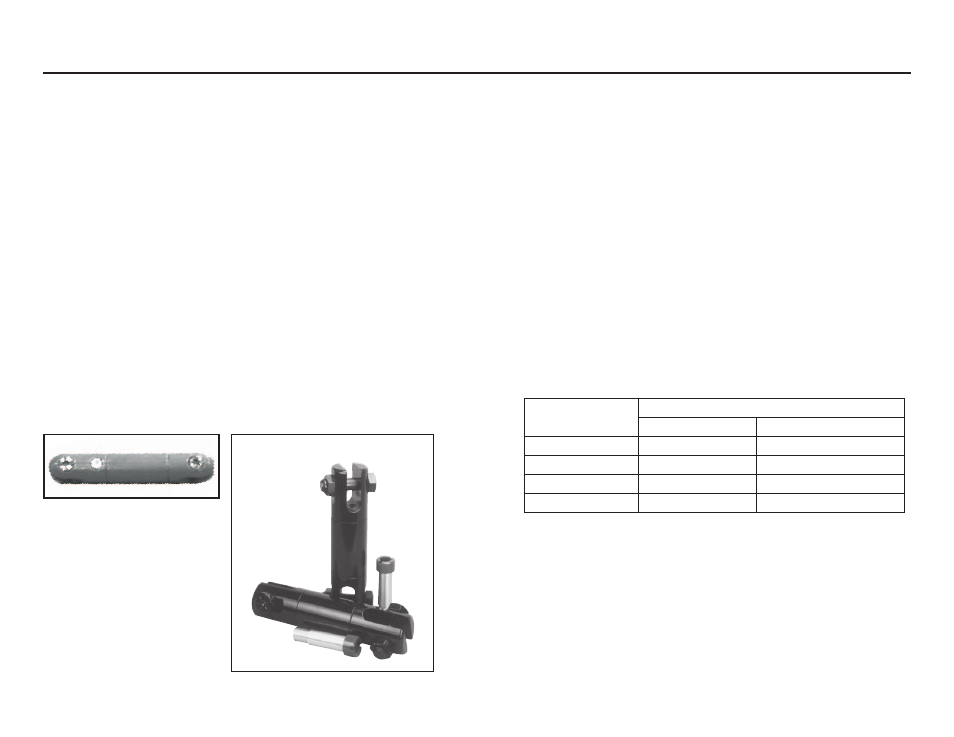
2.
The bearings and seals must be assembled as shown in the
swivel drawing (see Diagram 1 or 2).
3. Slide the bearings onto the break pin’s shaft (see Table 2 for correct
replacement break pin). Do not force the bearings - it could damage
the pin.
4. Apply Threadlocking Primer to the threads of the center pin and to the
threads on the externally threaded head. Apply Removable
Threadlocking Compound to the same threads. Do not apply
Threadlocking Compound to clevis pin (1
1
⁄
4
" & 1
3
⁄
8
") or clevis bolt or
nut (1
5
⁄
8
" - 4").
5. Insert the break pin and bearings into the
swivel body. Screw the
break pin into the internally threaded head and tighten until snug.
Do
not overtighten.
6. Torque break pin and externally threaded head to the following
specifications table (Table 1):
7. Using hole in swivel body, re-drill hole thru Center Break Pin. Press
Roll Pin thru Head and Center Break Pin until Roll Pin is centered in
Head (1
5
⁄
8
" - 4" swivels only).
8. Screw External Threaded Head back into the Body. Screw until snug
and then align Setscrew holes. Install Setscrew in Body and Head
(1
5
⁄
8
" - 4" swivels only).
1
1
⁄
4
" & 1
3
⁄
8
" Dia. Swivel
1
5
⁄
8
" - 4" Dia. Swivel
Swivel
Diameter
Torque Value
Break Pin
External Threaded Head
1 1/4"
10-15 in-lbs
20-25 ft-lbs
1 3/8"
10-15 in-lbs
20-25 ft-lbs
1 5/8"
15-20 in-lbs
90-100 ft-lbs
2" - 4"
15-20 in-lbs
120-130 ft-lbs
Table 1