4 auxiliary front panel power/sleep led connector, 5 front panel connector – chiliGREEN D915GAGL User Manual
Page 74
Intel Desktop Board D915GAV/D915GAG Technical Product Specification
74
2.8.2.4
Auxiliary Front Panel Power/Sleep LED Connector
Pins 1 and 3 of this connector duplicate the signals on pins 2 and 4 of the front panel connector.
Table 34. Auxiliary Front Panel Power/Sleep LED Connector
Pin Signal
Name
In/Out
Description
1
HDR_BLNK_GRN
Out
Front panel green LED
2 Not
connected
3
HDR_BLNK_YEL
Out
Front panel yellow LED
2.8.2.5
Front Panel Connector
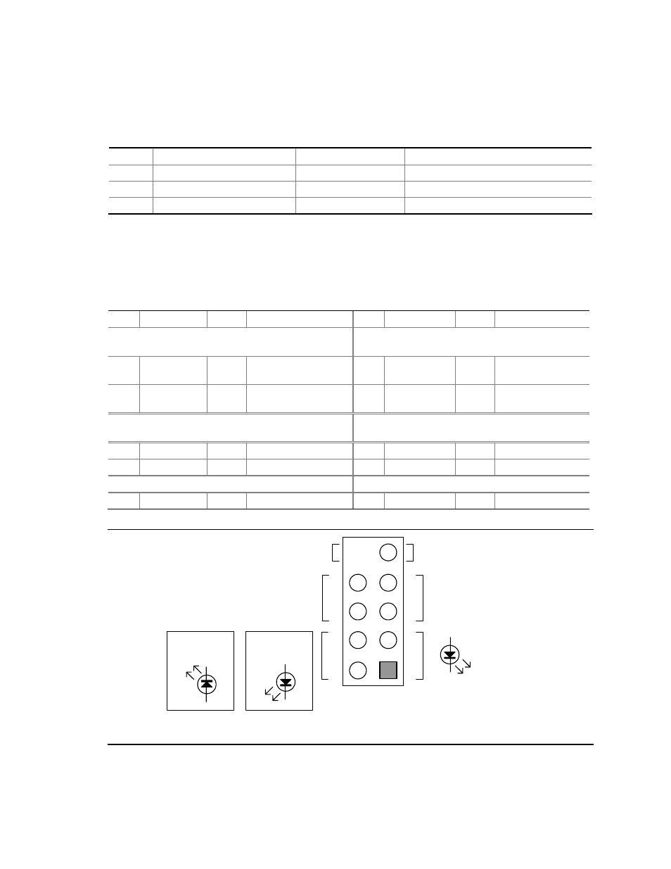
This section describes the functions of the front panel connector. Table 35 lists the signal names of
the front panel connector. Figure 21 is a connection diagram for the front panel connector.
Table 35. Front Panel Connector
Pin Signal
In/Out
Description
Pin Signal
In/Out
Description
Hard Drive Activity LED
[Yellow]
Power LED
[Green]
1
HD_PWR
Out
Hard disk LED pull-up
(750
Ω) to +5 V
2 HDR_BLNK_
GRN
Out
Front panel green
LED
3
HAD#
Out
Hard disk active LED
4
HDR_BLNK_
YEL
Out
Front panel yellow
LED
Reset Switch
[Purple]
On/Off Switch
[Red]
5 Ground
Ground
6 FPBUT_IN In Power
switch
7 FP_RESET#
In Reset
switch
8 Ground
Ground
Power Not
Connected
9
+5
V Power
10
N/C
Not
connected
Pu
rp
le
OM17000
Hard Drive
Activity LED
Reset
Switch
+5 V DC
N/C
Power
Switch
8
6
4
2
9
7
5
3
1
−
+
Single-colored
Power LED
−
+
Dual-colored
Power LED
+
−
Yel
low
Green
R
ed
Figure 21. Connection Diagram for Front Panel Connector