95 installation diagram – Blue Sea Systems 1801 Vessel Systems Monitor VSM 422 User Manual
Page 50
95
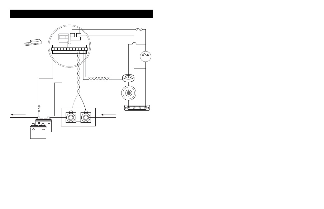
INSTALLATION DIAGRAM
Specifications subject to change. See www.bluesea.com for current information.
A
B
1
1
12
3
1
2
C
2
2 3 4 5 6 7 8 9 10 11
From negative
DC distribution
(all loads and
sources)
Fuse
(5 Amp)
AC
Reverse connections
#11 and #12
if kW ≠ positive
AC
LOADS
AC VOLTAGE
AND FREQUENCY
AC CURRENT
H
N
TEMPERATURE
SENSOR
can be connected in
either order
BATTERY
1
To Battery Switch
EXTERNAL SHUNT
Battery Side
Load Side
AC
COIL
BACK OF
THE METER
Fuse (0.5 Amp)
Install shunt for DC current measurement:
IMPORTANT! The shunt must be installed in the negative line to avoid
damage. Positive voltage applied to terminals #9 and #10 will cause damage
to the meter.
Install the shunt at any point in the DC negative feed line.Short sense
wires minimize voltage loss and interference, and result in the most
accurate metering.
There must be no loads connected to the battery terminal or the shunt of
Battery 1 or the Amp-Hour Function will not operate correctly.