Warning, Winter shutdown (90+ furnaces), Furnace maintenance – Bryant 359BAV User Manual
Page 5: Labeling, Pressure switches, Air filters/monthly, Replacement filters, Filter replacement
5
Two Stage
On\Off
Knob
INLET
OF
N
O
O
N
O
OFF
A07684
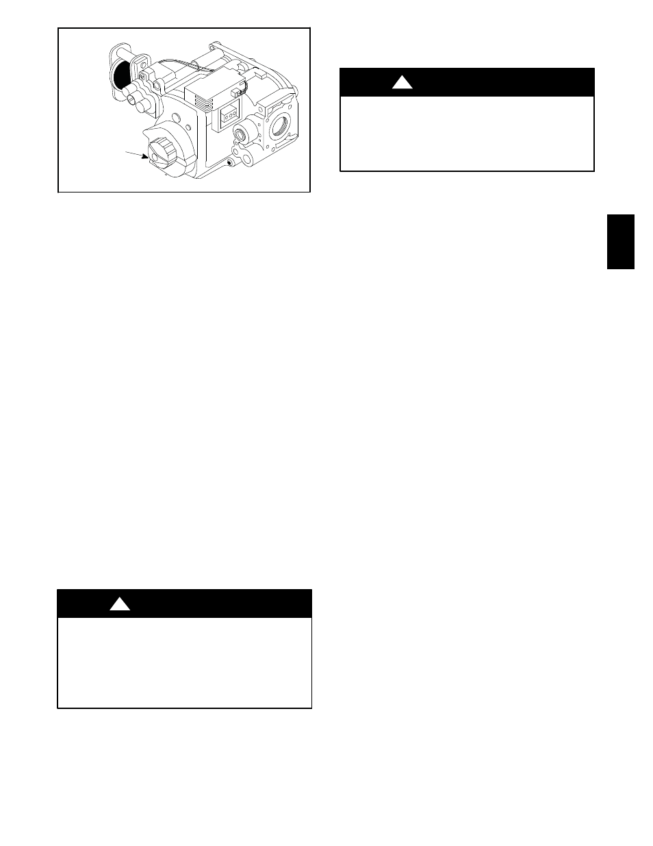
Fig. 3 -- Gas Control Valve
2. Have someone check the structure frequently during cold
weather to make sure it is warm enough to prevent pipes
from freezing. Instruct them to call a qualified service
agency to call to provide service, if required.
--or--
3. Install a reliable remote sensing device that will notify
somebody of freezing conditions within the home.
Winter Shutdown (90+ Furnaces)
If you go away during the winter months and do not leave the heat
on in your home, the plastic transition box and the condensate trap
on the furnace must be protected from freeze damage. (See Fig. 2)
1. Disconnect the 1/2” I.D. rubber hose from the vent drain fit-
ting (or tee) that is located downstream of the combustion
blower. Insert a funnel into the hose and pour four (4)
ounces of sanitary type (RV) antifreeze into the condensate
trap. Reconnect the 1/2” I.D. rubber hose to the stub on the
vent drain fitting. Secure with the hose clamp.
2. Disconnect the 5/8” I.D. rubber hose from the condensate
trap. Insert a funnel into the hose and pour four (4) ounces
of sanitary type (RV) antifreeze into the plastic transition
box. Squeeze the hose together near the end and quickly re-
connect the 5/8” I.D. rubber hose to the stub on the con-
densate trap. Secure with the hose clamp.
3. When you return home, your furnace will be ready to start,
as it is not necessary to drain the antifreeze from the furnace.
Furnace Maintenance
Have your furnace inspected and serviced on an annual basis
(before the heating season) by a qualified service agency.
Labeling
ELECTRICAL SHOCK HAZARD
Failure to follow this warning could result in personal injury
or death.
Label all wires prior to disconnection when servicing controls.
Verify proper operation after servicing. Only qualified service
agencies should attempt electrical service.
!
WARNING
Pressure Switches
During regular yearly maintenance, check for cracks in any tubes
on the pressure switches.
ELECTRICAL SHOCK HAZARD
Failure to follow this warning could result in personal injury
or death.
Turn off electrical power to furnace before performing any
maintenance or removing panels or doors.
!
WARNING
Air Filters/Monthly
The air filter(s) should be inspected at least monthly and cleaned or
replaced as required. There are many types of filters that are
commonly used. Washable filters (constructed of aluminum mesh,
foam, or reinforced fibers) may be cleaned by soaking in mild
detergent and rinsing with water. The fiberglass disposable type
should be REPLACED before it becomes clogged. Other filter
types should be serviced in accordance with the manufacturer’s
recommendations.
Remember that dirty filters are the most common cause of
inadequate heating or cooling performance.
Replacement Filters
If the filter is not located at or within the furnace, it should be
located somewhere in the return--air duct system.
The recommended sizes and types of filters that may be used with
your furnace are based on the furnace’s heating gas input rate (and
cooling system capacity, if so equipped).
Replacement filters should be of the same type and size as the
original filters, to ensure adequate air flow and filtering. A
disposable low velocity filter can be replaced with a washable high
velocity type. Do not replace a high velocity filter with a
disposable low velocity filter, except as permitted below.
If a cleanable (high--velocity) filter(s) is to be replaced with a
disposable (low--velocity) filter(s), the airflow area of the filter(s)
must be doubled (i.e., a second filter of the same size must be
installed so that only half of the air goes through each filter). A
second return--air duct to the furnace may be required in which to
install the second filter. Modification of a furnace installation shall
comply with the local installation code and the furnace installation
instructions, and shall be made only by a Qualified Service
Agency.
NOTE: Some filters are marked with an arrow to indicate the
proper direction of air flow through the filter. The air flow
direction will be towards the blower motor. Make sure filter is
installed correctly.
Filter Replacement
The filter may be installed inside the bottom of the furnace blower
compartment, or the filter(s) rack may be installed under the
furnace or on either or both sides of the furnace. A plastic end
cap(s) is inserted in the filter rack(s) after the filter(s) is installed.
The end cap keeps air from escaping around the open end of the
filter rack. See Fig. 4 and Fig. 5 for side and bottom locations.
Rack end cap is similar for bottom mounted filter rack.
Filter rack(s) attached to the outside of the furnace is made so the
filter simply slides out one end for removal.
359B
A
V