Barranca Diamond HP30 Slab Saw User Manual
Page 16
16
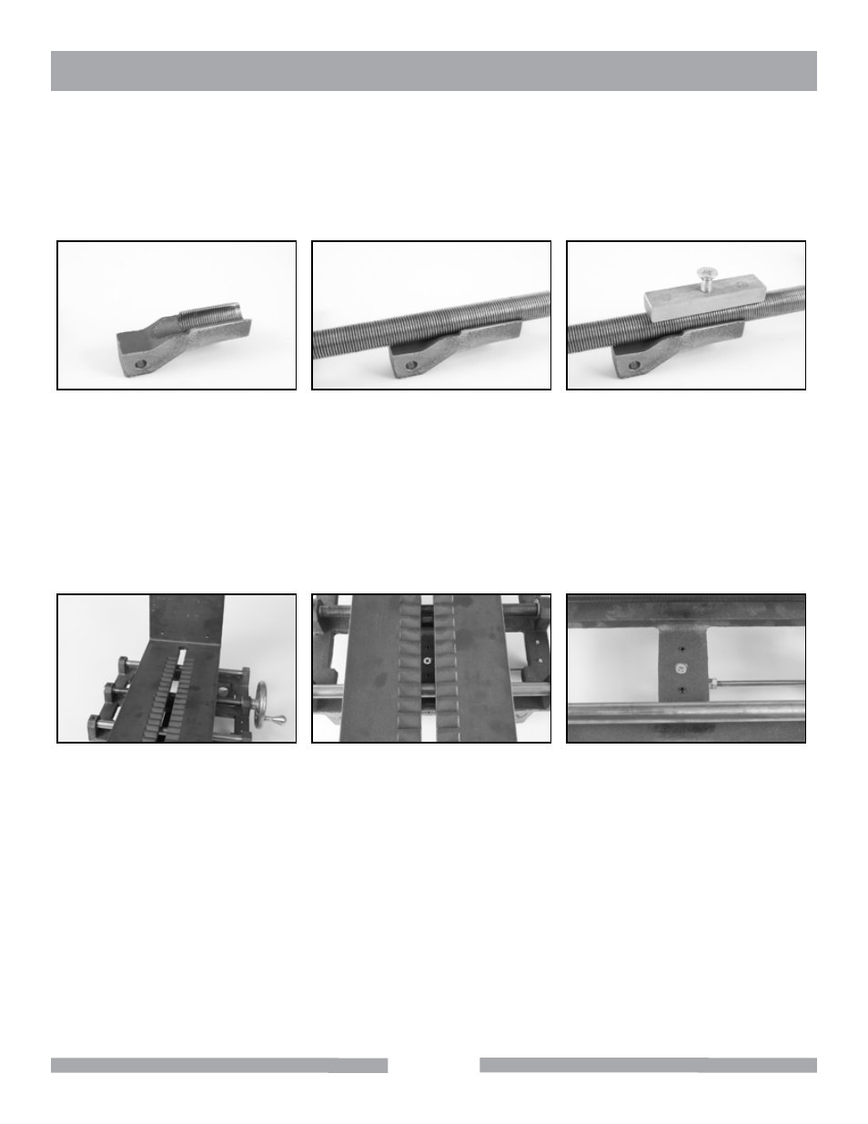
Clutch Adjustment Procedure
The clutch system on HP Slab Saw is comprised of three main components: a bronze clutch shoe (fig. 1) that
is raised and lowered by a lever activated cam (not shown), the feed screw (fig. 2) that drives the vise carriage
when the clutch assembly is engaged, and the brass pressure block (fig. 3) that applies downward pressure
against the feed screw to keep it engaged with the clutch block.
Fig. 1: Clutch block
Fig. 2: Clutch block & feed
screw
Fig. 3: Clutch assembly with
pressure block
Over time, the brass pressure block can wear due to contact with the rotating feed screw. This can cause the
clutch block to not properly engage the feed screw. Should the clutch block not fully engage the carriage will
not travel properly and the position of the pressure block will need to be adjusted. To access the pressure block
adjustments, use the cross feed handle to move the center slot in the vise assembly (fig. 4) so that the clutch
block adjustment screws are visible through the slot (fig. 5). In Figure 6, the vise has been removed from the
carriage assembly to clearly show the clutch block adjustment screws.
Fig 4: Vise assembly
Fig 5: Vise assembly centered
over clutch block adjustment
screws
Fig 6: Clutch block adjustment
screws
HP30
OPERATIONS & ADJUSTMENTS