Barranca Diamond FIREBALL 2 AXLE SPHERE MACHINE User Manual
Page 9
Barranca Diamond Products Phone: 310-523-5867 www.barrancadiamnd.com
START UP
Prior to placing the sphere cups on the grinding head shafts, open the moveable head to a position along
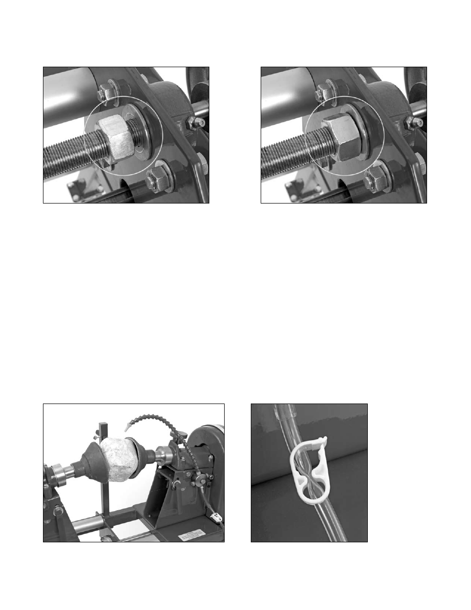
the horizontal plane of the sphere machine. This is done by first loosening the brass nut on the thread bar
adjacent to the crank handle and rotating it along the shaft a few inches (fig. 1).
Fig. 1 Brass nut loosened
Fig. 2 Brass nut tightened
This will allow free adjustment of the moveable head to the desired position. Liberally grease the head shaft
threads prior to installing sphere cups. Place a sphere cup on each of the 1/2"-13 threaded shafts of both the
fixed and moveable heads and hand tighten snuggly against the sphere cup holder face. The cups can be
tightened with use of a pipe wrench on the sphere cup shank to ensure cups are snuggly secured to the 1/2"-
13 thread (do not over tighten). Once cups are attached, place rock sphere material between cups and slowly
rotate crank wheel by hand (clockwise) stopping at a point that still allows some rotation of sphere material
between cups. Once adjusted to desired position, lock the threaded horizontal adjustment brass nut against
the plate adjacent to the crank handle (fig. 2). Do not over-tighten.
Once the sphere material is in place between the grinding cups and the moveable head is adjusted and
locked, connect the water pump to the base of the Loc-Line hose manifold and submerge the pump in a 5
gallon bucket of water. Adjust the tip of the Loc-Line nozzle to direct water flow as close to the top of the
sphere material as possible. A constant flow of water onto the sphere material must be maintained to flush
the grindings and keep the diamond cups and pads (when Velcro pad mounting cups are used) in good
condition. Any loss of water to the grinding surface of the diamond cups or polishing resin pads during use of
the machine will likely result in short diamond tool life. You can reduce or increase the waterflow to the Loc-
Line nozzle by adjusting the flow restrictor that crimps the clear tubing between the Loc-Line assembly and
the water pump.
Loc-Line hose in position
Waterflow restrictor