Aquascape PRO-Fit Signature Series Skimmer (09019 & 29349) User Manual
Page 8
8
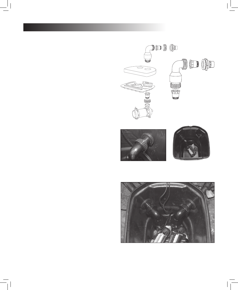
Fig. 1 Check Valve Assembly
Fig. Pump Assembly
NOTE: One pump shown. Your installation
may have two pumps.
Fig. 4 Apply silicone or Teflon tape (not
included) to the threads of the fitting.
Fig. One adaptor threads directly
into the pump, the other threads
directly into the bulkhead on the
back of the skimmer.
Installing the Pump,
Filter Rack and Filter Mat
STEP 9
• The Signature Series
™
check
valve comes with two adaptors
that replace the standard PVC
pipe sockets on each end of the
check valve
(See Fig. 1). One
adaptor threads directly into the
pump, the other threads directly
into the bulkhead on the back of
the skimmer that supplies water
to the BIOFALLS
®
filter. Apply sili-
cone or Teflon tape (not included)
to the threads of the fitting
(See
Fig. & 4).
• The 2nd hole located in the back
of the skimmer is for the overflow.
The overflow will help maintain
the maximum water level in the
pond after rainfall, ensuring that
your skimmer works properly
and water does not travel over
the edges of the liner and cause
problems with hydrostatic pres-
sure. Refer back to page 6 for
overflow information.
• Once inside the skimmer, feed the
electrical cord over the depression
located on the back, top edge of
the skimmer.
(See fig. 5)
• Set the Filter Rack inside the
skimmer.
(See fig. 6) Punch out
the corresponding die-cut hole
located on the skimmer filter mat
and insert the skimmer mat into
the filter.
(See fig. 7)
• If using Tsurumi or AquaSurge™
pump, please refer to check valve
assembly instructions for further
information.
Assembly of the
Adjustable Faceplate
in the Skimmer Basket
• The weir plate
(See fig. 8) fits onto
the slide plate and is attached with
2 large thumb screws into the cor-
responding threaded inserts.
• The slide assembly can now
be placed inside the basket
and attached with the 6 small
stainless screws threaded in
from outside face of the basket.
(See fig. 9 & 0)
• Place the basket in the skimmer.
(See fig. 1) The basket fits into
the front edge of the filter sup-
port rack. Please note that the
support rack is what supports the
basket. The tabs on the top edge
of the basket are not load bearing
and simply hold the basket up to
the face of the skimmer.
Assembly of the
Adjustable Faceplate
• The patent pending adjustable
faceplate allows the final water
level of the pond to be adjusted.
Please note that this feature is
for making final adjustments and
tweaks to the water level. It is
important the skimmer was set
to the proper water level to begin
with. You may find you’ll need to
reset the entire skimmer box if
making minor adjustments when
the adjustable liner plate does
not meet the desired water level.
• Make sure the pond is filled to
the desired level prior to making
final adjustments.
• Adjust the weir opening to the ap-
propriate water level by loosening
the thumbscrews and adjusting
as needed.
(See fig. ) There
should be approximately 3/4 inch
gap between the water level and
the top of the faceplate opening
to allow proper skimmer action.
• Dial-in the adjustable overflow
arm so that water rising past the
desired level will begin to trickle
down the overflow arm.
(See fig.
) Please note that we recom-
mend to re-silicone or Teflon tape
(not included) the threads of the
overflow fitting once the final
position is determined. Once the
overflow is set, the pond owner
should not readjust. Readjust-
ment may require the threads to
be re-siliconed or Teflon taped to
prevent water loss.
Fig. 5 Feed the electrical cord over the depression.
29888 PRO-Fit SS Skimmer Install8 8
3/21/07 1:43:31 PM