Continued on next page) – APG AGV-1000 Collision Avoidance user manual User Manual
Page 8
AGV-1000
Rev. A3, 10/08
8
Automation Products Group, Inc.
APG...Providing tailored solutions for measurement applications
Tel: 1/888/525-7300 • Fax: 1/435/753-7490 • www.apgsensors.com • [email protected]
• Wiring
The AGV-1000 utilizes plug and socket terminal-block wiring connections.
The system is designed to operate on 10 to 30 VDC. The supply voltage
connects to terminals 1 & 2 or 11 & 12. The AGV-1000 has six “Front-End”
circuits, each controlling a transducer. The terminals labeled FE(+) on the
diagram below, refer to the “Front End” circuits. Connect the transducer (+)
wires to the corresponding FE terminals. The T(-) terminals refer to the
transducer negative connections. The GND terminals are for grounding the
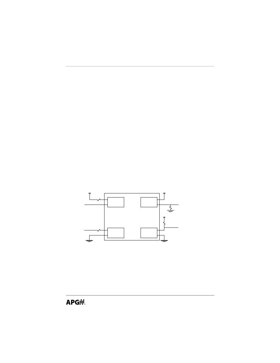
transducer cable shield wires. The IN and OUT terminals refer to the inputs and
outputs of the system. The options for wiring the inputs and outputs are shown
in the diagram below. To help reduce induced noise, all unused INPUTS should
be jumpered between the (+) and the corresponding (-) terminals.
NOTE: The maximum transducer cable length is 6 ft.
OR
Solid State Relay
Output Circuitry
OUT1(+)
OUT1(-)
Output Circuitry
OUT1(+)
OUT1(-)
+V
+V
Solid State Relay
OPTION 1
To Main Processor Input
OUTPUT at +V = Normal Condition
OUTPUT at GND = SLOW/STOP/ERROR
OPTION 2
To Main Processor Input
OUTPUT at Ground = Normal Condition
OUTPUT at +V = SLOW/STOP/ERROR
I(max) = 100 mA
R= 600 at 12 Volts (20 mA)
R = 1.2K at 24 Volts (20 mA)
OUTPUT
Relay = CLOSED = NORMAL
Relay = OPEN = ACTIVE
AGV-1000 Circuitry
+V
OPTION 2
Switch + VDC
0 V = Off
+V = ON
I(typ) = 10mA
INPUT
Voltage across input terminals = ON
IN(+) = IN(-) = OFF
IN1(+)
IN1(-)
IN1(+)
IN1(-)
OR
Input Circuitry
Opto-Isolated Input
Input Circuitry
Opto-Isolated Input
OPTION 1
Sink current to GND
IN(-) = GND = ON
IN(-) = FLOAT = OFF
10mA (typ)
(Continued on next page)