Wiring the pg7, 20 ma option (loop powered), Battery replacement – APG PG7 user manual User Manual
Page 25
Rev. A, 12/09
PG7
25
Automation Products Group, Inc.
APG...Providing tailored solutions for measurement applications
Tel: 1/888/525-7300 • Fax: 1/435/753-7490 • www.apgsensors.com • [email protected]
Wiring the PG7
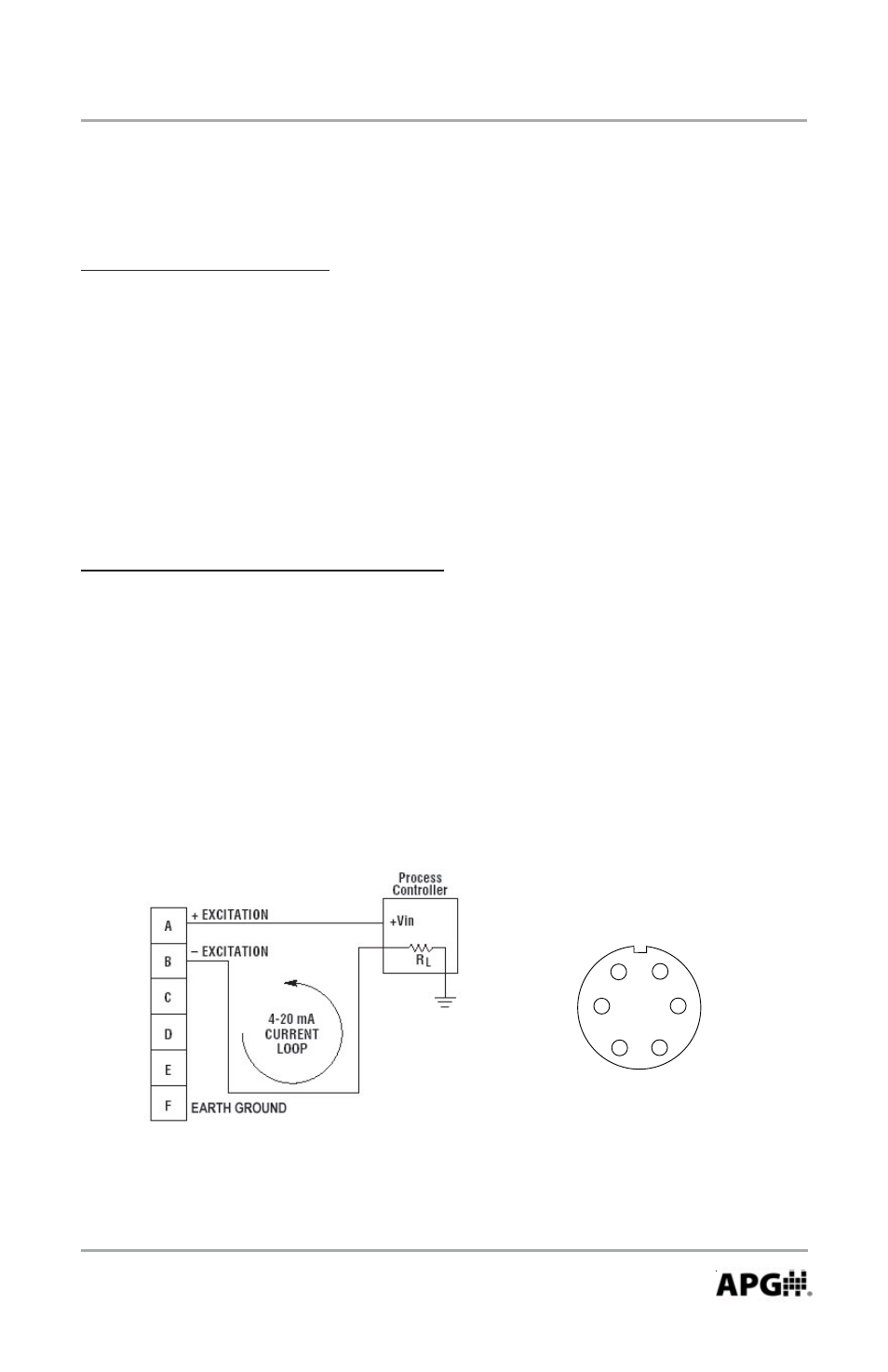
4-20 mA Option (loop powered):
NOTE 1: The supply voltage must be sufficient to maintain a minimum of 9
VDC after “dropping” voltage across the load resistance with the
output at 20mA. Example: If RL = 250 ohm then the “drop” is 0.02
Amps X 250 ohm = 5 volts. Therefore power supply minimum is 5 V +
9 V = 14V.
NOTE 2: Completion of the earth ground (Pin F) is recommended for proper
circuit protection.
A
F
B
E
C
D
6 Pin Connector
Battery Replacement:
Step 1: Press on the front bezel and turn counter-clockwise to release the bezel
from the gauge.
Step 2: Remove the front display to access the batteries.
Step 3: Replace the front display ensuring that the notch in the display aligns
with the tab on the gauge housing.
Step 4: Replace the bezel by lining up with the tabs on gauge while pressing
inward and twisting clockwise.