Anchor EVENT SERIES - PROFILE SIZE: 220MM X 100MM, INSTRUCTION SUPPLEMENT - WINDOW / HARD WALL INSTALLATION User Manual
Page 2
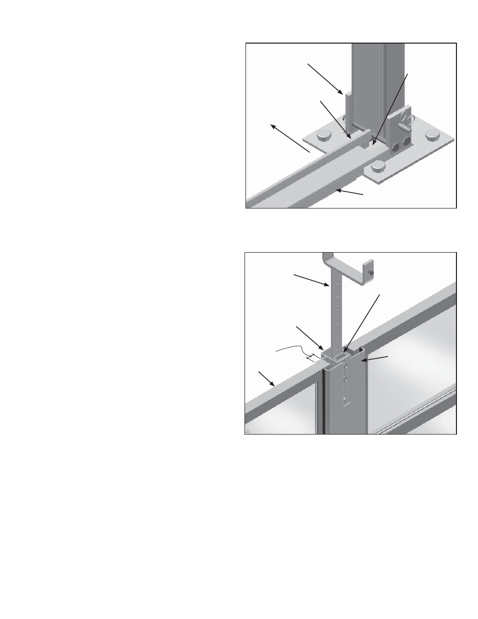
1. Install the wall base equally spaced between the
uprights. Position the wall base so that the back lip
is toward the interior of the tent. See Figure 1.
2. Install the U-Channels in the uprights by engag-
ing the “L” leg into the outside kedar groove of the
upright and rotating the U-Channel toward the interi-
or of the tent until the flat portion of the “U” contacts
the upright. At this point, if the wall base is posi-
tioned correctly, the U-Channel will drop down into
the notch at each end of the wall base.
3. Remove the bolts, washers and pressure plates from
all of the intermediate posts. Save for re-use after
the wall panels are installed.
4. Remove the bolts and washers from the adapter
forks and slide the vertical portion of the fork inside
the top of the post, but outward of the spacer tube inside the post. See Figure 2.
Note:
DO NOT insert the fork inside the spacer tube. Re-install the washers and bolts in the vertical por-
tion of the adapter fork and loosely tighten so the fork is allowed to slide in and out.
5. At about 48” away from the side U-Channel, posi-
tion the first intermediate post on the wall base so
that the “Z” clip on the bottom of the post engages
the back lip of the wall base. See Figure 3. Rotate
the post to a plumb position while engaging the “U”
portion of the fork with the purlin above. Slide the
adapter fork up until the bottom of the “U” portion of
the fork contacts the bottom of the purlin. Snuggly
tighten the bolts that fasten the fork to the post.
Note: These bolts and the setscrew in the fork must
be securely tightened once the wall panels are in
position.
6. The install kit assembly is now ready to receive the
first wall panel.
7. The orientation of the wall panel is correct when the
smaller pane of glass is on the bottom and the glaz-
ing stops are toward the interior of the tent.
8. First engage one side of the wall panel into the U-
Channel, then pivot the opposite side toward the intermediate post until the inside face of the wall panel
contacts the lip on the wall base. (Note: If the intermediate post is in the way, slide it out of the way to allow
the panel to pivot back against the lip on the wall base.) Once the wall panel is in place, slide the interme-
diate post back toward the wall panel until the leg of the post overlaps the outside face of the wall panel by
approximately ¾”. Install the pressure plate to the intermediate post, but do not tighten the bolts so that the
adjoining wall panel can be placed on the opposite side of the intermediate post. See Figure 2.
Figure 1
To inside of
Building
Back lip
Notch that
receives U-
channel
Wall Base
Building Upright and
Base Plate
INSTALL KIT ASSEMBLY AND WALL PANEL INSTALLATION
2
Adapter Fork
Pressure Plate
Intermediate
Post Assembly
Figure 2
Spacer Tube
Approx. 3/4”
overlap.
Wall Panel