Idr0, Getting started, A] [b – Allen&Heath iDR0 User Manual
Page 7: Idr0 user guide 7
iDR0 User Guide
7
iLive-176 44 faders, 176 strips
CHOOSE SURFACE SIZE
2
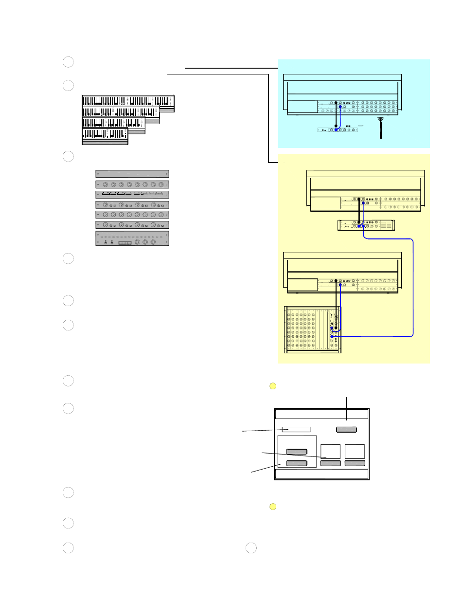
CONNECT UP THE SYSTEM
Audio network - Plug iDR0 ESA OUT to Surface ESA IN (1x CAT5 cable)
4
Control network - Plug iDR0 NETWORK to Surface NETWORK (1x CAT5 cable)
If split FOH/Monitror system - Plug iDR0 ESB IN from master iDR10 ESB out
Connect mains power leads
Connect backup iPS10 power supplies if required
POWER UP THE SYSTEM
The system should connect and boot up within 2 minutes
5
Switch on the MixRack and Surface
LOAD A TEMPLATE SHOW AS A STARTING POINT
Press + to expand the list
6
Press UTILITY / Configuration / Show Manager
Select TEMPLATES from the left window
iLive-144 36 faders, 144 strips
iLive-112 28 faders, 112 strips
iLive-80 20 faders, 80 strips
Audio Sync/Networks
Audio Clock Source
Select and Recall a show as a starting point for using your system
iDR0_LR_24in8out
Stand alone mixer with audio I/O at rear of surface
SLAVE_MON_8m8st
Monitor console slave system
SLAVE_FOH_LR
FOH console slave system
CHECK AUDIO CLOCK AND ETHERSOUND SETTINGS
8
Press MIXRACK / Mixer Pref / Audio Sync Networks
INTERNAL
Stand alone mixer with audio I/O at rear of surface
Check Audio Clock setting (Chooses the source to syncronise the digital audio)
ESB
Slave FOH or Monitor system with ESB digital mic splitter
Check EtherSound configuration (Configures the digital audio network mapping)
MASTER
Stand alone mixer with audio I/O at rear of surface
MASTER/SLAVE
Slave FOH or Monitor system with ESB digital mic splitter
Check Channel Source settings (Chooses which inputs feed the channels)
Local Inputs
Stand alone mixer with audio I/O at rear of surface
ESB Inputs
Slave FOH or Monitor system with ESB digital mic splitter
CHECK INPUT SOCKET MAPPING
9
From IP channel PREAMP screen check for required socket patching
Surface Slot A-D
Stand alone mixer
ESB ch 1-64
Slave FOH or Monitor system with ESB digital mic splitter
[A]
[B]
[A]
[A]
[B]
CHECK OUTPUT SOCKET MAPPING
10
Press OUTPUTS / Surface to check which signals feed the Surface output sockets
Surface Slot A-D
Stand alone mixer outputs or local slave outputs
Restore ESA Defaults
SET
Quick Input Setup
Global ESB Input
Global Local Input
SET
SET
SET
SET
Master
Slave
ESB Config
The iDR0 is similar to the iDR10 but without the slots for audio I/O cards. It is the iLive 'brain' with DSP mix engine, control and audio network interfaces.
iDR0 provides a compact solution for systems using EtherSound as a digital mic splitter, or as a stand alone mixer using audio at the rear of the surface.
16 outputs, takes up 2 slots
11
RECALL SCENE FOR SURFACE SIZE
7
Gives you a logical layout for your Surface size
Press SCENES - Select and recall scene STRIPnnn where nnn = surface size
[A]
[B]
[B]
[B]
[A]
[B]
[A]
[B]
[A]
[B]
12
MORE...
Refer to the iLive REFERENCE GUIDE for more on configuring and using iLive
Refer to the FIRMWARE RELEASE NOTES for more on new features
Refer to WWW.ALLEN-HEATH.COM for the latest information on iLive
ARCHIVE YOUR SETTINGS
Name and archive your setup as a Show for each iLive (eg. FOH and Monitor)
You could also store your settings as a Scene memory (Select All)
eg. If it has been changed using an external application such as ES Monitor
You can resore the EtherSound configuration to standard mapping using this:
If the Surface audio does not appear where you expect it:
The ESB Master/Slave setting are not stored in the memories
NOTE: The Audio Clock Source is stored in Scene and Show memories
CHOOSE YOUR APPLICATION
Stand alone mixer with audio at rear of surface
GETTING STARTED
iDR0
1
AP7284 iss.1 V1.2
Split FOH/Monitor dual console system
ALLEN
&
H
EA
TH
iDR
-6
4
MI
X E
N
GIN
E
COMPACT STAND ALONE MIXER
SPLIT FOH / MONITOR SYSTEM
Audio on rear of surface
ES audio
Network control
Analogue multicore
Mix engine
SLAVE system
MASTER system
ESA local audio
Network control
ESB mic splitter
Mix engine
iDR0
iDR0
ESA local audio
Network control
CHOOSE AUDIO MODULES FOR LOCAL AUDIO AT THE SURFACE
Load up to 4x 8 channel audio modules, eg - 24 inputs + 8 outputs
3
MIC/LINE
M-MICIN-A
BLANK
M-BLANK-A
DUAL MIC
M-DUALIN-A
DIGITAL IN
M-DIGIN-A
LINE OUT
M-LINEOUT-A
DIGITAL OUT
M-DIGOUT-A
MULTI OUT
M-MULTI-OUT-A