Ilive, Using the idr0 – Allen&Heath iDR0 User Manual
Page 12
12
iDR0 User Guide
Using the iDR0
There are several ways the iDR0 can be used within an iLive system. It is just one of many
component options that may be configured to satisfy a host of demanding audio mixing applications.
We recommend that you visit the Allen & Heath web site for information on the full range of iLive
components available. You can also download additional application drawings which illustrate the
versatility of iLive in satisfying many basic and advanced applications.
Refer also to the iDR0 Getting Started Guide AP7284 printed earlier in this guide and also to the iLive
System Reference Guide AP6526. Further information on the latest features is available in the
Release Notes which come with each firmware release. Check our web site to download the latest
version of iLive firmware.
The following pages illustrate some of the iDR0 applications. They are based on preconfigured
‘template’ Show memories which can be recalled from the Surface UTILITY / Configuration / Show
Manager screen. These give you a good starting point by configuring a recognisable classic
architecture and surface layout. You can edit these and name and store your customised
configurations as User Shows.
A
B
D
C
A1-8 = CH1-8
B1-8 = CH9-16
D1-8 = CH17-24
C1-4 = AUX1-4
C5-6 = LR
Load Show
8x GRP = 4m 2st
16x AUX = 10m 1st 4FX
MAIN = LR
8x MTX = 4m 2st
CONFIG
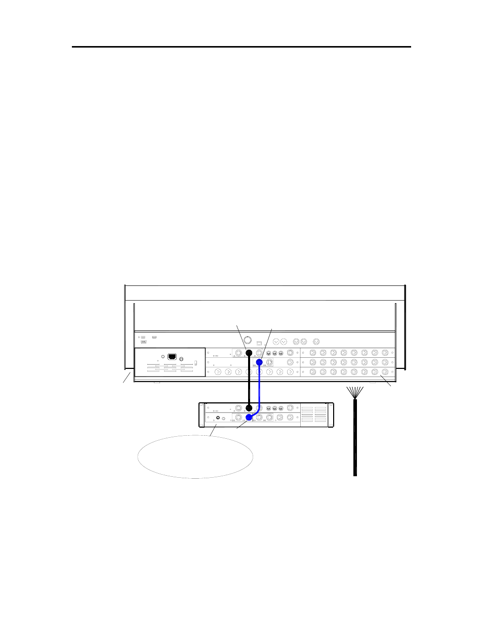
APPLICATION EXAMPLE - iDR0 WITH iLIVE AS A STAND ALONE MIXER
24 inputs, 8 outputs compact system.
iDR0_LR_24in8out
AUDIO CLOCK = INTERNAL
ESB CONFIG = MASTER
CH SOURCE = LOCAL INPUTS
ESA OUT
ETHERNET
CAT5
ETHERSOUND
CAT5
ESA IN
NETWORK
iDR0
HEADPHONES and TALKBACK
Set options using TOUCHSCREEN = MIXRACK / Mixer Pref / Audio Sync Networks
All I/O in back of surface = 24 inputs, 4 aux, LR, 2 matrix
FOH/Monitor
C7-8 = ST MTX 1-2
AUDIO
COPPER MULTICORE
iLive