Level control, Level control configuration, Mute switch enable – Allen&Heath GR05 User Manual
Page 16: Switch zone select, 16 gr05 user guide
16
GR05 User Guide
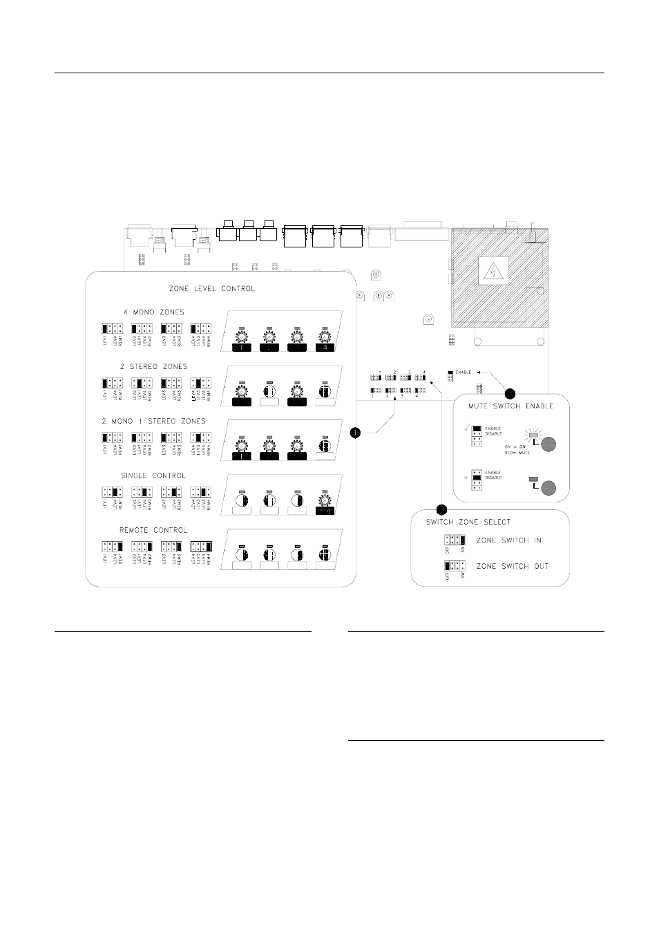
Level Control
This section describes the installer configuration of the VCA path level control.
For each output you can select which front panel control affects the level. This
lets you control stereo zones or groups of outputs with a single level control.
You can also assign which outputs will be turned on or off by the front panel
switch. The switch function can be disabled if required.
To configure the unit switch off power, remove the top cover and adjust the
jumper links as shown. Avoid the power supply components shown greyed out
on the diagram.
Level Control Configuration
Each output has a 4 position link which determines how
the VCA level is controlled. Three positions set which
front panel control affects the level. The fourth position
selects remote control. If remote is selected the front
panel controls will have no effect. Fit the link in one of
the available positions.
The examples show how the unit can be configured for
individual or grouped level control. Use the hole plugs
provided to blank out the controls which are not used.
This system avoids operator confusion by locking away
redundant controls.
Mute Switch Enable
The front panel on/off (mute) switch is enabled or
disabled by setting this link as shown. When disabled
the switch LED is off. When enabled the LED is either
green (on) or red (off). Depending on the installation
you may wish to turn all outputs, or just selected
outputs, on or off with this switch.
Switch Zone Select
For each output select whether or not the mute switch
will affect the signal. Set the link to SW or OFF as
shown. Note that the switch will have no effect if it has
been disabled as described previously.
out 2
out 1
out 3
out 4
out 2
out 1
out 3
out 4
out 2
out 1
out 4
out 3
mute
mute
out 1
out 2
out 3
out 4
out 1
out 2
out 3
out 4