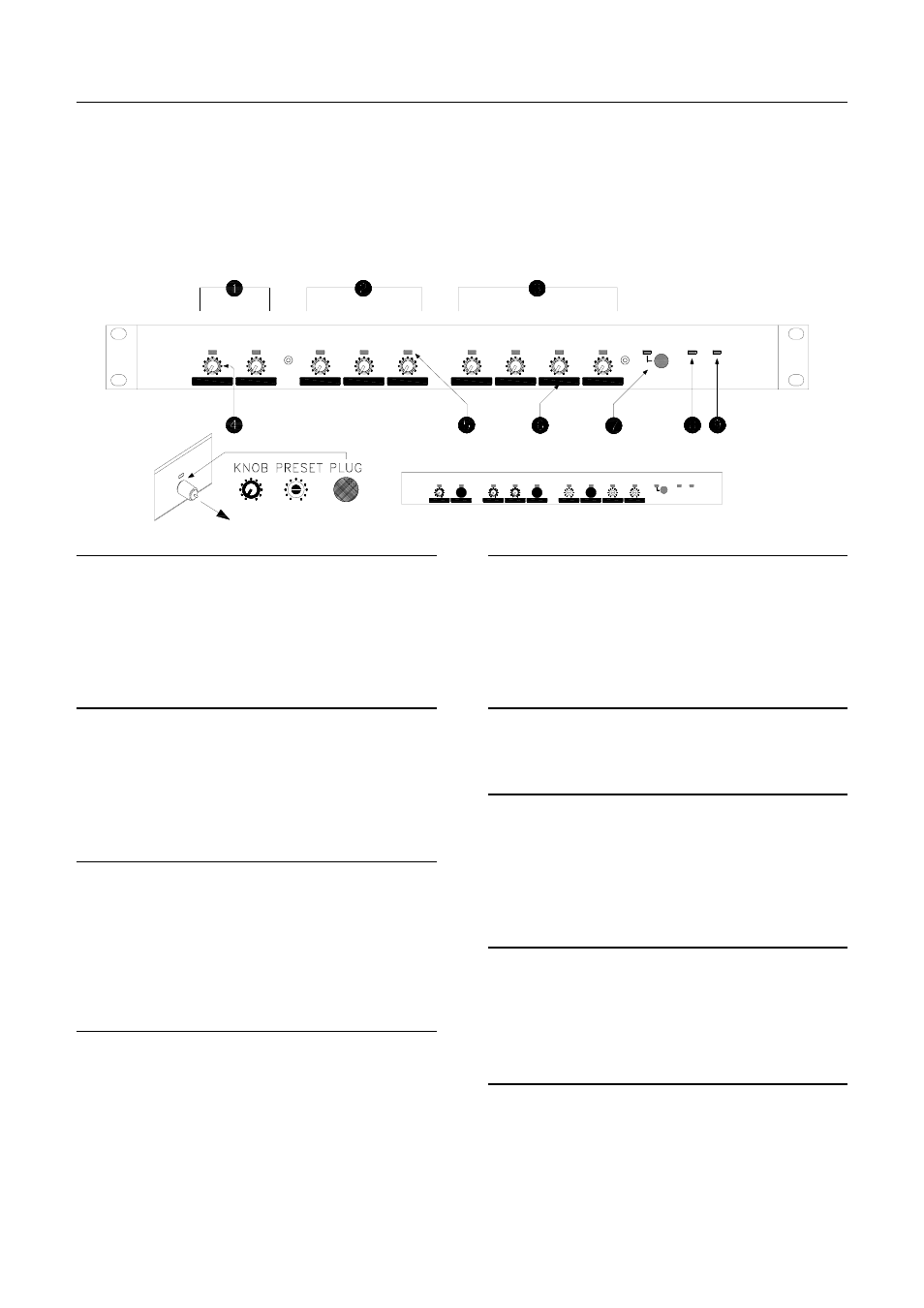
Front panel, Mic/line inputs 1,2, Line inputs 3,4,5 – Allen&Heath GR05 User Manual
Page 10: Zone outputs 1,2,3,4, Level control, Signal meter, Control ident blocks, Output mute switch and indicator, Ducking status indicator, Power status indicator
10
GR05 User Guide
Front Panel
The front panel control layout is deliberately uncluttered and simple. These are
the controls that are used by the non-technical operator who does not need to
understand how the unit has been configured or what the controls do
technically. Control function and access can be configured by the installer. A
row of 3-colour LED indicators display the signal levels and system status.
These are invaluable for system setup and diagnostics.
Mic/Line Inputs 1,2
The sensitivity of the input stage is matched to the
connected microphone using the rear panel gain
trimmer. The front panel level control adjusts the level of
the signal to all routed outputs. Fully anti-clockwise is
signal off, clockwise signal on. A 3-colour LED displays
pre-level input signal status.
Line Inputs 3,4,5
The sensitivity of the input stage is matched to the
connected equipment using the internal jumper links.
The front panel level control adjusts the level of the
signal to all routed outputs. Fully anti-clockwise is signal
off, clockwise signal on. A 3-colour LED displays pre-
level input signal status.
Zone Outputs 1,2,3,4
These front panel controls adjust the level of the output
signal routed through the VCA paths. Fully anti-
clockwise is signal off, clockwise signal on. They may
be disabled, for example when using remote level
control. They may also be linked for stereo or group
control. A 3-colour LED displays post-level output
signal status.
Level Control
Input level controls are always active. Output level
controls may be disabled or grouped by internal links.
All controls may be set in 3 ways:
Knob fitted for operator control
Knob removed for screwdriver preset
Hole plug fitted to lock out control
To remove the knob simply pull it forwards. To refit the
knob align the knob hole with the flat on the control
spindle.
Signal Meter
A 3-colour LED meter for each input and output displays
the signal level. Input signals are displayed before the
level control, output signals after the level control.
Green = Signal present (from –12dB)
Yellow = Nominal 0dB signal
Red
= Peak 5dB before clipping
Control Ident Blocks
These blocks can be marked or labelled for control
identification.
Output Mute switch and Indicator
This front panel switch turns the outputs on or off. The
switch function can be disabled for selected outputs by
setting internal option links.
Off
= Switch disabled
Green = Selected outputs on
Red
= Selected outputs muted (off)
Ducking Status Indicator
Displays the status of the ducking system.
Off
= No ducking active
Green = Internal ducking only active
Red
= External ducking only active
Yellow = Both internal and external active
Power Status Indicator
Displays the status of the power system.
Off
= No power applied
Green = Mains power on only
Red
= Backup power on only
Yellow = Mains and backup power on
st line 5
ALLEN&HEATH
AUDIO ZONE MIXER
GR05
mic/line 1
mic/line 2
st line 3
st line 4
out 1
out 3
out 2
out 4
mute
ducking
power
mic/line 2
ALLEN&HEATH
AUDIO ZONE MIXER
GR05
mic/line 1
ducking
out 1
st line 4
st line 3
st line 5
out 2
out 3
out 4
mute
power