Gl2200 – Allen&Heath GL2200 USER GUIDE User Manual
Page 22
GL2200
U
SER
G
UIDE
22
D
UAL
M
ODE
AUX
aux 1- 4
L- R
PRE
POST
L R
AUX 1 & 2
AUX 3 & 4
MONO
pre-fade aux sends
STAGE MONITOR
L
1
3
MONO
4
2
R
3
R
M
4
L
SEND
5
INSERT
6
R
INSERT
L
MONITOR
INSERT
2-TRACK
RETURN
4
3
INSERT
STEREO
RETURN
1
2
1
TALKBACK
STEREO
RETURN
INSERT
2
1
INSERT
IN
12
16
R
MIC
L/MONO
15
STEREO
OUT
10
DIRECT
9
OUT
DIRECT
OUT
8
DIRECT
IN
14
R
MIC
11
L/MONO
13
STEREO
IN
LINE
MIC/LINE
IN
10
INSERT
IN
LINE
MIC/LINE
IN
9
INSERT
LINE
MIC/LINE
IN
IN
8
INSERT
DIRECT
OUT
7
DIRECT
OUT
6
DIRECT
OUT
5
OUT
4
DIRECT
LINE
MIC/LINE
IN
IN
7
INSERT
MIC/LINE
IN
LINE
IN
INSERT
6
MIC/LINE
IN
LINE
IN
INSERT
5
IN
LINE
IN
MIC/LINE
4
INSERT
OUT
3
DIRECT
2
OUT
DIRECT
OUT
1
DIRECT
IN
LINE
MIC/LINE
IN
3
INSERT
IN
IN
LINE
MIC/LINE
2
INSERT
IN
LINE
MIC/LINE
IN
1
INSERT
GRAPHIC
EQUALISERS
inserts
4
2
3
Post fader aux sends
returns
EFFECTS
returns
aux 6
aux 5
pre-fade aux sends
STAGE MONITOR
COMPRESSOR / LIMITER
inserts
L
R
(compressor)
PROCESSOR
insert
SIGNAL
MULTITRACK RECORDER
groups 1 & 2
direct outs 1-6
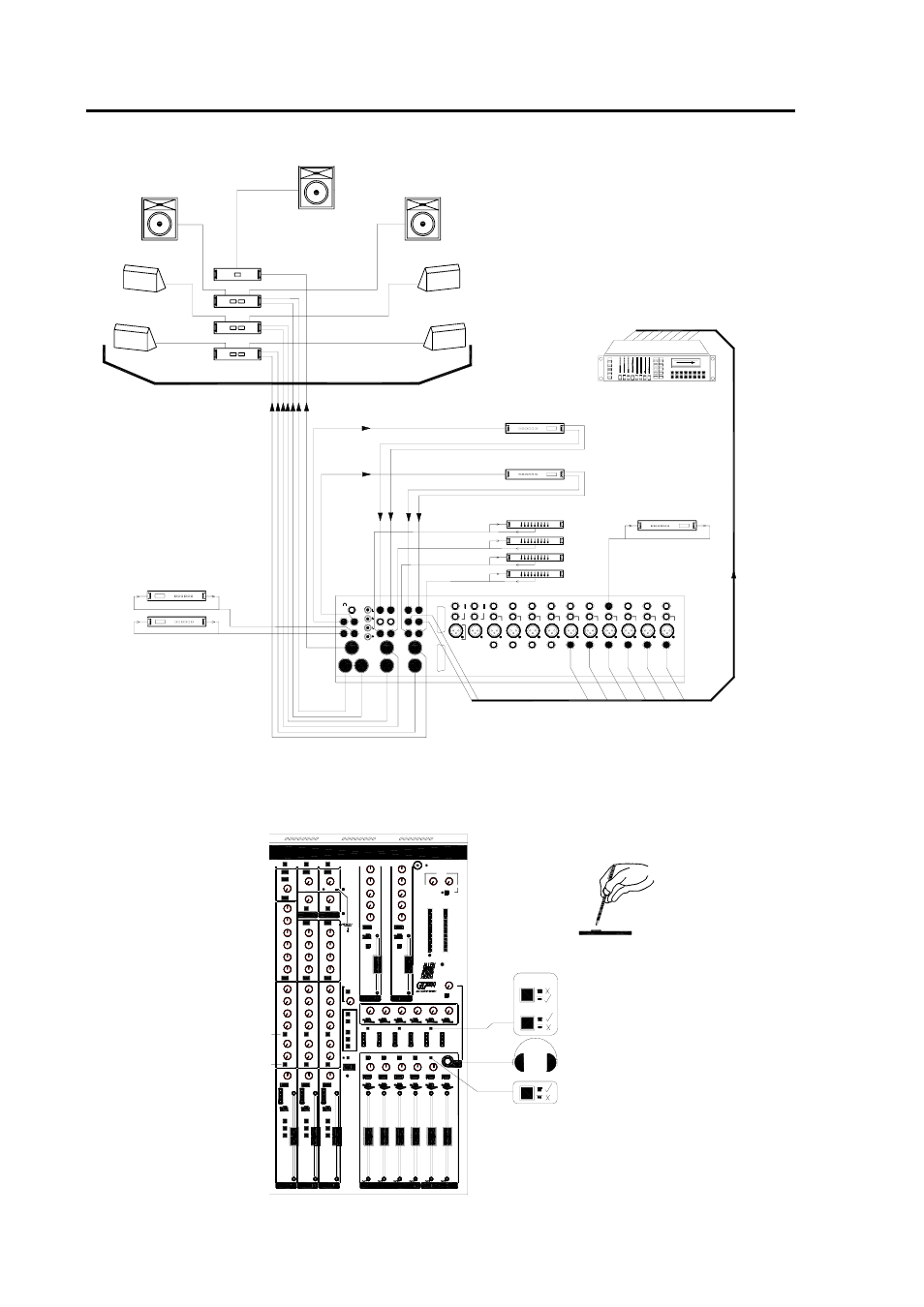
GRAPHIC EQUALISERS
Graphic equalisers plugged into the inserts are an
invaluable aid to reducing on-stage acoustic
feedback and enhancing the clarity of the monitors.
COMPRESSORS/LIMITERS
These are used to prevent
excessive peaks overloading the
amplification system, for
example in club installations
subject to sound level control.
This example shows the
console configured to control
a Left, Right and Centre Front
of House system with 4 full
feature stage monitor mixes.
Stage monitor sends aux 1-4
are set pre-fade so that the
signal level is not affected by
the fader position and the
FOH mix.
Aux 5-6 are set post-fade to
access two effects devices
whose outputs are added to
the L-R mix via stereo returns
1 and 2. Alternatively, these
may be connected to the
stereo channels.
The channel and output
inserts may be used for
outboard effects and signal
processors such as
compressors, limiters and
graphic equalisers.
These switches are recessed
to avoid accidental operation.
Set using a pen tip or pointed
object.
Set the AUX REVERSE switch
to the down position (below
panel) to route aux mixes 1-4
through groups 1-4. Set L-R
switch in the up position for
conventional operation.
Set LR SUM MONO switch to
up for mono out (L+R sum).
MULTITRACK RECORDING
Connect the inputs of the multitrack to the aux
jack outputs. These are now the group mix
outputs. Any unused multitrack inputs can be
connected to the channel direct out sockets to
record each channel on a separate track for mix
down later.