Build the framework, Aeiwp s, Atdip s – Best IP29M Series User Manual
Page 8: Warning
- 8 -
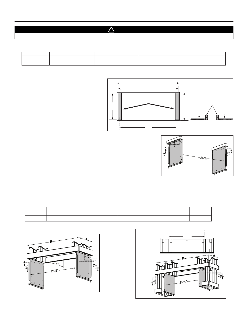
In the ceiling material, cut-out a 28¾” x 12½” max.
opening over the installation location. Install two
supporting studs inside the cut-out at dimensions
shown beside.
7. BUILD THE FRAMEWORK
7.1 S
UGGESTED
F
RAMEWORK FOR
I
NSTALLATION WITH
D
ECORATIVE
F
LUE
C
OVER
AEIWP S
ERIES
7.2 S
UGGESTED
F
RAMEWORK FOR
I
NSTALLATION WITH
D
RYWALL
T
RIM
ATDIP S
ERIES
HD0235
27¼”
C
C
L
C
L
HD0237
F
RAMEWORK
54’’ H
OOD
F
RAMEWORK
42’’ H
OOD
WARNING
When building framework, always follow all applicable construction codes and standards.
!
The framework must be sized to support the total weight of the hood. Refer to the table below for total weight of the hood, according to the
type of blower chosen.
H
OOD
W
IDTH
WITH
P6
INTERIOR BLOWER
WITH
P12
INTERIOR BLOWER
WITH
I
N
-
LINE OR
E
XT
.
BLOWERS
(
ROUGH
-
IN PLATE ONLY
)
42”
71
LB
84
LB
52
LB
54”
86
LB
99
LB
67
LB
28½”
12½”
max.
27”
C
L
28¾”
HD0227A
C
L
12 /
8
”
5
Studs flush
with ceiling material
ceiling
material
ceiling
material
S
UPPORTING
S
TUDS
Using provided wood screws no. 10 x 1.5” and washers, assemble both mounting brackets
(included with the optional decorative flue cover) to the framework. See illustration beside.
HD0228A
Below is the suggested framework for both 42” and 54” width hoods to be installed with drywall trim ATDIP Series. Refer to the table
and illustrations below for the dimensions according to the hood width. Using provided wood screws no. 10 x 1.5” and washers,
assemble both mounting brackets (included with the optional drywall trim) to the framework.
H
OOD WIDTH
A
WITH
5/8”
DRYWALL
A
WITH
1/2”
DRYWALL
B
WITH
5/8”
DRYWALL
B
WITH
1/2”
DRYWALL
C
42”
11
5
⁄
8
”
11
7
⁄
8
”
28
5
⁄
8
”
28
7
⁄
8
”
10”
MINIMUM
54”
11
5
⁄
8
”
11
7
⁄
8
”
40
5
⁄
8
”
40
7
⁄
8
”
10”
MINIMUM
F
RAMEWORK
T
OP
V
IEW