Danger, Blade measure here anvil – Echo CH123DH Owners Manual v.2 User Manual
Page 20
12 INCH CHIPPER
16
SERVICE & MAINTENANCE
BEFORE INSPECTING OR SERVICING ANY PART OF THIS MACHINE, SHUT OFF POWER SOURCE, REMOVE KEY,
DISCONNECT THE BATTERY CABLES AND MAKE SURE ALL MOVING PARTS HAVE COME TO A COMPLETE STOP.
WARNING
With the chipper motor running and the engagement
1.
handle DISENGAGED, raise and secure the feed
roller (Section 4.6).
If the anvil edge is damaged or worn unevenly, remove
anvil and use one of the other three edges. If all edges
are damaged or worn unevenly, replace the anvil.
NOTE
5.6 SETTING BLADE CLEARANCE
Ensure that the feed roller is raised and secure before
entering the feed chute. Failure to do so can result in
serious injury or death.
DANGER
Shut the engine off, remove the key, and allow the rotor
2.
to come to a complete stop.
Lift the knife access cover and secure with the lockup
3.
pin (Sec. 4.8).
Rotate the disk until a chipping blade is even with the
4.
anvil.
Secure the chipper disk to prevent movement during
5.
adjustment (for example, by wedging a piece of wood
between a rotor paddle and the housing).
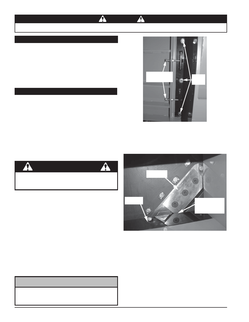
Loosen the three 1/2" x 1-1/2" bolts that secure the
6.
anvil to the chipper housing (access is from underneath
machine, see picture).
Loosen the two 3/8" adjustment nuts located inside the
7.
anvil backplate (access is from underneath machine,
see picture).
Adjustment
Nuts
Anvil
Bolts
View of anvil bolts and adjustment nuts from underneath machine
Blade
Measure
Here
Anvil
Measuring clearance between blade and anvil
Secure the disk to prevent movement during installation.
1.
Place a blade on the disk and attach with three 5/8"
2.
x 3" bolts and nuts. Torque to 230 ft-lbs. Repeat for
remaining blades.
Lower the knife access cover.
3.
Secure the knife access cover to the chipper housing
4.
using two 1/2" x 1-1/4" bolts, nuts and washers.
5.5 INSTALLING THE BLADES
Check the clearance every 8 hours of operation and adjust
if needed. The chipping anvil is reversible. All four sides
of the anvil can be used for chipping. Use the following
guide when setting the blade clearance:
If you are chipping materials that are primarily
•
smaller
than 6 inches, use an anvil gap of 1/4” to 3/8”.
If the materials are
•
6 inches and larger, use an
anvil gap of 3/8” to 7/16”.
To adjust the anvil:
Measure the clearance between the chipping blade
8.
and the anvil from inside the feed chute. Adjust both
nuts equally until the clearance between the chipping
blades and the anvil is correct.
Rotate the disk to ensure there is proper clearance be-
9.
tween ALL four chipping blades and the anvil. The anvil
gap may be different for each blade. Ensure the gap is
set for the closest blade. Adjust anvil if necessary.
Once proper clearance is achieved, tighten the three
10.
1/2" x 1-1/2" bolts to secure the anvil to the frame.
Tighten the two 3/8" adjustment nuts located inside the
11.
anvil backplate.
Lower the knife access cover by removing the lock pin,
12.
and turning the wing nut on the jack to the left.
Remove the feed roller lock up pin, lower the feed roller
13.
and resume operation.