English – Echo CH123DH Owners Manual v.2 User Manual
Page 17
12 INCH CHIPPER
13
ENGLISH
OPERATION
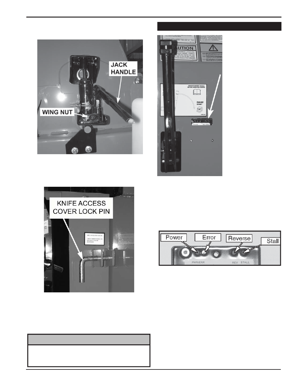
Lift the engine hood and locate the knife access cover
3.
jack inside the chipper housing next to the hydraulic
fluid reservoir (see below).
Turn the wing nut located on the bottom of the jack to
4.
the right and pump the handle.
Secure the cover using the lock pin located on the
5.
outside of the chipper housing (see below).
To lower the cover, remove the lock pin and turn the
6.
wing nut located on the jack to the left to release the
hydraulic pressure.
Secure the knife access cover to the chipper housing
7.
using two 1/2" x 1-14" bolts, nuts and washers.
When closing the rotor cover, make sure the bolts are
securely tightened. If they are not, the safety switch
may respond as though the battery is dead.
NOTE
The chipper is equipped
with a pre-programmed
feed controller located
next to the engagement
handle. The controller
monitors chipper rotor
RPM, controls the feed
r o l l e r, a n d p r o v i d e s
routine maintenance
alerts.
The controller functions
are further detailed
below:
The controller
1.
monitors the RPM of the
chipper rotor. If the RPM
drops below the preset
range, the feed roller
is stopped. When the
RPM reach an accept-
able level, the feed roller
is reengaged.
The controller
2.
also has a “try again”
feature. If the hydraulic pressure of the feed roller is
too high (if the feed roller becomes obstructed) the
controller will reverse the feed roller, removing the
unchipped material. The controller will then reengage
the roller forward and try to feed the material again. If
this cycle continues, remove the obstruction manually.
Trim or reposition material if necessary.
Lights on the controller give the following information:
3.
Error light will flash 10 times every 100 hours
•
of operation upon startup to indicate the engine
oil should be changed.
Error light will flash 5 times every 15 hours of
•
operation upon startup to indicate the chipper
blades should be sharpened.
Steady power light indicates controller operat-
•
ing normally, blinking power light indicates low
or no power to the controller.
To reset service alerts, locate the light green wire in
4.
the engine compartment next to the hour meter. Con-
nect the green wire to the red wire connector for five
seconds.
4.9 FEED CONTROLLER