Optimal rotor and engine rpm – Echo CH611DH Instruction v.7 User Manual
Page 5
Instruction Sheet
5
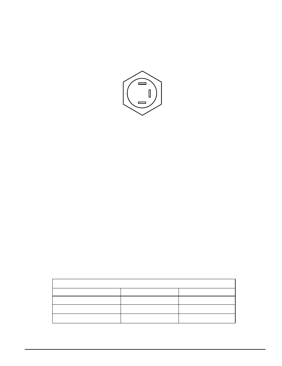
WHITE
BLUE
RED/YELLOW
8. hOOK Up ThE LED
Connect the three wires on the Plus 1 harness to the LED as shown below.
If the wires are correctly connected, the light will flash red upon initial startup. If the light flashes green, the wires are
reversed. After initial startup, see Control Light Flash Codes chart for an explaination of all color codes.
9. OpERATION
Upon initial startup, make sure the chipper is in Neutral (Stop) position. If the chipper feed control is in any other
1.
position, the LED will flash red and forward feed will not be available.
Upon initial startup, if the chipper is in Neutral position, the LED will flash green, indicating that the RPM is not high
2.
enough to chip (see Optimal Rotor and Engine RPM chart).
Increase RPM gradually until the LED is solid green. Forward feed is now available.
3.
See the Control Light Flash Codes table on the following page for a complete explaination of all flash codes provided
4.
by the LED. Save these instructions for future reference.
10. OpTIONAL REMOVAL OF SMARTRELAy
Once you have used the Plus 1 controller long enough to verify that it works correctly, the SmartRelay controller can be
removed along with the box that it is located in. A plate to cover the SmartRelay opening is provided with this kit, along
with the necessary hardware.
11. OpTIMAL ROTOR AND ENGINE RpM
OpTIMAL ROTOR AND ENGINE RpM
Chipper Model
Rotor RpM
Engine RpM
CH611DH (76628)
1800
3000
CH6670H (76624)
1675
3780
CH6993H (76635)
1675
3780