3 install flush face couplers, 4 pre-operation, 3 install flush face couplers 4.4 pre-operation – Echo CH500H Owners Manual v.2 User Manual
Page 14: Warning, Important
5" and 8" Skid Steer Chipper
10
OPERATION
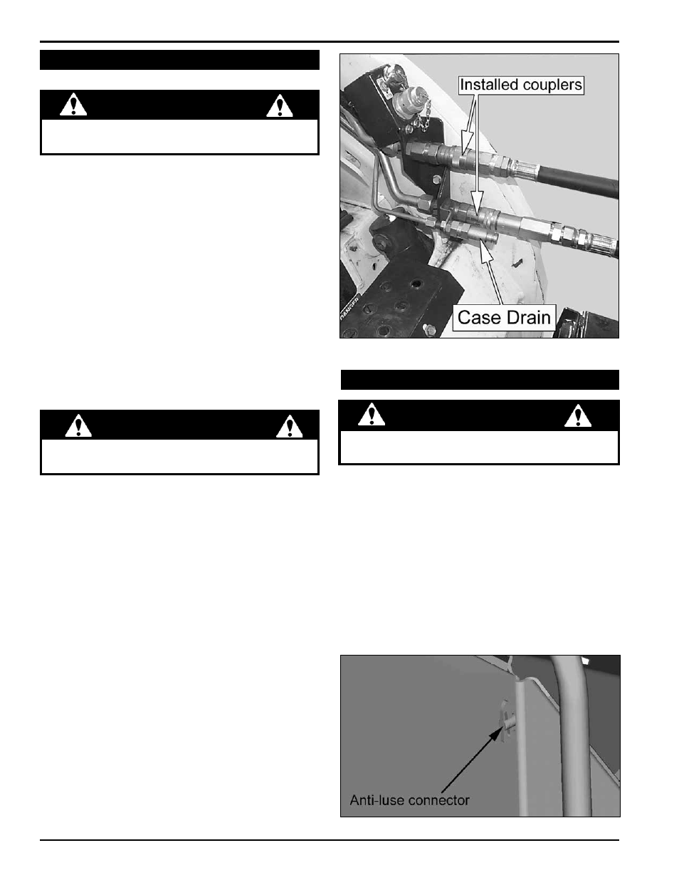
Figure 4.3 - Installed Couplers
The skid steer chipper is equipped to attach to flush face
couplers (Figure 4.3). the chipper is shipped with -12
sized hydraulic couplers fitted on the hoses. A tie wrap is
used to indicate the pressure line. Be sure to connect the
hydraulic hoses to the proper ports.
If the skid steer is fitted with anything other than -12 sized
flush face couplers on the main lines, it will be necessary
to replace the couplers supplied with the chipper.
the chippers are also equipped with a case drain hose.
the case drain is used to eliminate pressure on the
chipper’s hydraulic motor. The motor is rated for 250 to
300 psi of back pressure.
Most high flow skid steer loaders are equipped with a case
drain line. Standard flow skid steer loaders typically are not.
If the back pressure is over 300 psi, a case drain line
will have to be added. Contact your skid steer dealer for
details.
Hydraulic lines may be under pressure due to testing
done at the factory.
4.3 InsTall FlusH FaCe CouPlers
warnInG
NOt addiNg a CaSe draiN liNe vOidS tHe
CHiPPer WarraNty!
ImPorTanT
To ConneCT:
1. Before connecting, make sure to relieve the hydraulic
pressure in the skid steer using the skid steer system.
2. remove dirt and debris from the surface of the couplers.
3. visually check the couplers for damage; replace if
damage is found.
4. install the male coupler into the female coupler. Full
connection is made when the ball release sleeve slides
forward on the female coupler.
5. turn the sleeve so that it is rotated away from the
locking pin to prevent accidental disconnection.
6. repeat the procedure for all hoses, including the
smaller case drain hose.
To DIsConneCT:
1. relieve the hydraulic pressure in the skid steer using
the skid steer system.
2. rotate the ball sleeve so the grooves are aligned with
the pins in the female coupler.
3. retract the sleeve on the female coupler until the
couplers disconnect.
4. repeat the procedure for all hoses.
1. Wear appropriate eye, face, and hearing protection.
Wear gloves that fit tight against the wrist.
2. remove the latch from the side of the feed table.
3. lower the chipper feed table.
4. Check that the feed roller is clear of material.
5. Place the feed roller control in the “stop” position.
6. Push down the latch and rotate the discharge chute to
the desired position.
7. release the handle and move the chute until it locks
the chute in position.
Figure 4.5 - Antiluce Connector
4.4 Pre-oPeraTIon
do not attempt to bypass the safety systems of the
skid steer loader.
warnInG