4 attach extension tray, 5 attach discharge tube, 4 attach extension tray 2.5 attach discharge tube – Echo CH911DH Owners Manual v.7 User Manual
Page 11: English, Warning
9 INCH CHIPPER
7
ENGLISH
ASSEMBLY
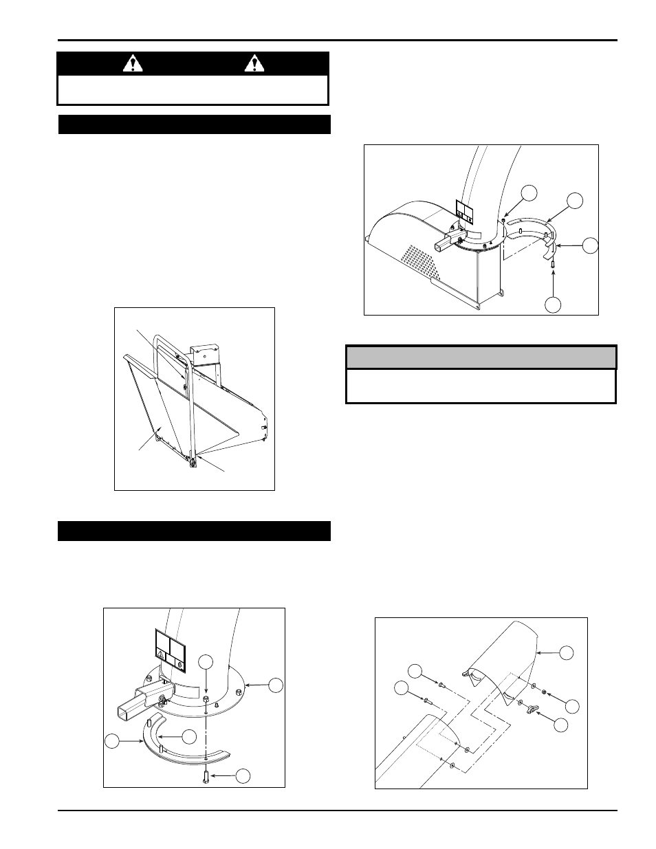
warninG
Do not operate this unit without the chipper chute correctly installed.
Rotating cutting blades can cause serious personal injury.
2.4 aTTach eXTension TraY
1. Tilt the extension tray up, so the bottom of the tray is
facing outward (Figure 2.3). Slide the extension tray lips
between the extension hinge and chipper chute lips.
2. Tilt the extension tray down until the tray rests on the
extension hinge, and the extension tray lips contact the
back of the chipper chute lips.
3. Insert five 3/8 x 1" carriage bolts (included in owner's kit)
through the extension tray and hinge. Secure the bolts
with washers and nylock nuts from the bottom.
4. Attach the chute support weldment to the middle hole
of the chipper chute by using the existing bolt.
EXTENSION
TRAY LIP
EXTENSION
HINGE
CHIPPER
CHUTE LIP
Figure 2.3, Attaching the extension tray
Keep nuts as tight as possible while allowing the
discharge tube to freely turn.
noTe
1. Attach one clamping ring (1) and one spacer ring (2) to
discharge tube base (3) using three 3/8 x 1 1/4" bolts
(4) and nylock nuts (5). Tighten leaving 1/16" gap to
assist in mounting to flange. See Figure 2.4.
2. Slide the tube onto the mounting flange on the chipper
frame. The discharge clamp (1) should slide underneath
the lip of the flange. Tighten the bolts to secure it.
3. Install the second half of the spacer (2) and clamp ring
(1) on the discharge tube with 3/8 x 1-1/4" bolts (4) and
nylock nuts (5).
1
2
3
4
5
6
7
9
8
10
Figure 2.6, Attach discharge deflector
Figure 2.4, Attach clamp ring and spacer
Figure 2.5, Attach discharge tube
4. lubricate the chute by applying grease to the grease
zerk at the base of the chute. Rotate the chute and
apply grease until the chute rotates freely.
5. Rotate the tube 360 degrees and lock it in place with
the lock pin to make sure it is mounted correctly.
6. Attach the discharge deflector (6) to the discharge tube.
Connect the deflector with two 5/16 X 1 1/4" bolts (7)
through the lower hole in the discharge tube. Run these
bolts through the inside of the tube, washer, deflector,
washer, and then knob (8).
7. Finish bolting the deflector to the tube with two 5/16 x
1" bolts (9) through the end hole in the discharge tube
and secure with 5/16 washers & nylock nuts (10).
1
2
4
5
2.5 aTTach DischarGe TuBe