9 adjusting/replacing drive belt, 10 replacing bearings – Echo CH9540H Owners Manual v.5 User Manual
Page 24
PTO CHIPPERS
20
SERVICE & MAINTENANCE
BeFORe INSPecTING OR SeRVIcING ANY PART OF ThIS MAchINe, ShuT OFF POWeR SOuRce,
ANd MAke SuRe All MOVING PARTS hAVe cOMe TO A cOMPleTe STOP.
WaRNING
5.10 REpLaCING bEaRINGS
5.9 adJuSTING/REpLaCING dRIvE bELT
disengage PTO and shut off tractor engine.
1.
Remove PTO shaft from tractor; disconnect machine
2.
from 3 pt. hitch.
check the condition of the drive belt annually or after every
25 hours of operation, whichever comes first. If the belt is
cracked, worn, frayed, or stretched, replace it.
To replace the belt:
Remove round shield connected to belt guard that
3.
covers PTO shaft by removing two 5/16" nuts.
Remove belt guard covering pulleys and belts.
4.
Remove spring loaded idler pulley off belts and remove
5.
belt.
Remove hitch Support.
6.
Install new belt and reverse above instructions to
7.
complete belt replacement.
Rotate discharge to the right side of the machine.
1.
Remove the two 3/8 inch retaining bolts holding the
access cover to the main frame assembly. Tilt the
access cover open to allow access to the rotor.
Remove upper and lower belt guards (10-5/16 bolts).
2.
FRoNT bEaRING REmovaL
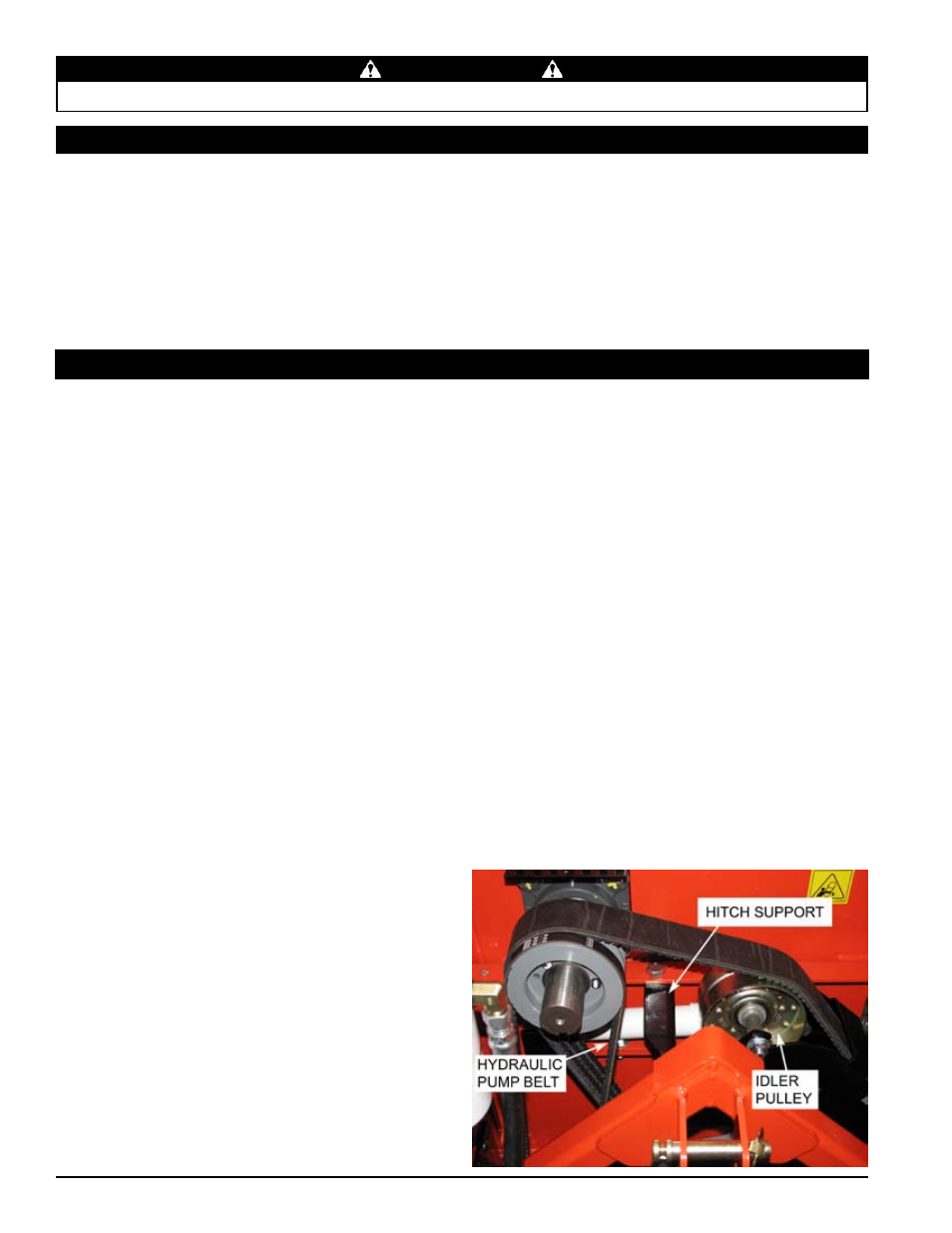
Remove the hitch Support.
3.
loosen the bolts holding the hydraulic pump bracket to
4.
the 3-point, slide the bracket up and remove hydraulic
pump belt.
Remove the idler tensioning springs, and remove the
5.
1/2 bolt holding the idler pulley in place.
Remove the drive belt.
6.
Taking the bolts out of the pulley and reinserting them
7.
into the empty holes, slowly tighten each bolt in a
rotating clockwise direction to remove the bushing and
sheave from
the rotor shaft.
loosen the set screw holding the spacer in place and
8.
remove. If rear bearing does not need to be removed
go to step 14.
REaR bEaRING REmovaL
lift up the feed roller and insert the retaining pin to
9.
hold in place.
Remove the protective cap.
10.
Remove the 3/8 bolt holding the retaining spacer and
11.
remove the spacer.
Remove the four 1/2 inch bolts on each rotor bearing
12.
and loosen the two set screws on each bearing. (Note:
You may have to clean the shaft with emery cloth.)
Remove and replace with new bearings.
13.
Put the bolts back in the bearings and slide into place.
14.
Tighten bolts to 75 ft-lbs (102 Nm). Slide rear collar
back into place and insert 3/8 bolt.
Taking a rubber mallet, tap the rotor shaft until the rear
15.
collar is tight against the rear bearing. Tighten the bolt
and lock the set screws on both bearings. Torque to
180 inch-lbs (20 Nm). Reinstall front collar and tighten
the cap screw. Make sure the speed sensor is aligned
and gapped properly.
Reinstall the rear rotor protective cap. Slide the bushing
16.
on and tighten set screw, then slide the sheave on.
Insert bolts into the sheave and tighten in a clockwise
direction. Torque to 108 inch-lbs (12 Nm).
check the alignment of pulleys with a straight edge
17.
and adjust if needed.
Replace the drive belt.
18.
Replace the idler and tighten. Reinstall tensioning
19.
springs.
Bolt the hitch support back in its original position.
20.
close cover and replace bolts.
21.
Replace the hydraulic pump belt. Readjust hydraulic
22.
pump belt tension by sliding the hydraulic pump in the
mounting slots. Tighten bolts.
Replace belt guard and resume operation.
23.
Start tractor engine and engage PTO drive clutch (see
24.
tractor owner’s manual). Increase engine speed to rated
PTO RPM position. Test unit; readjust pulleys and belt
tension if needed.