Important – JLG 80HX_HX+6_HXER ANSI Service Manual User Manual
Page 90
SECTION 4 - BOOM & PLATFORM
4-10
– JLG Lift –
3120271
4.3
WEAR PADS
1.
Shim up wear pads within 1/16 in. (1.59 mm) toler-
ance between wear pad and adjacent surface.
2.
Replace wear pads when worn within 1/8 in. (3.18
mm) of threaded insert.
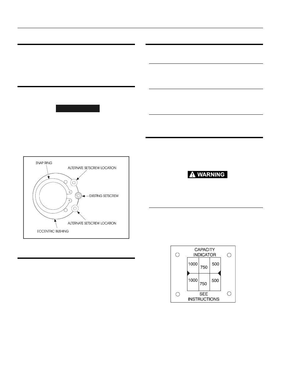
4.4
TELESCOPE CYLINDER ECCENTRIC
BUSHING
IMPORTANT
RELOCATE ALTERNATE SETSCREW HOLE ONLY WHEN REPLAC-
ING ECCENTRIC BUSHING.
When replacing the eccentric bushings, drill 5/16" dia. x 3/
4" deep, tap 3/8-16NC x 9/16" deep for a new setscrew
(bushing to boom) either above or below original holes.
Allow enough room between the holes for strength while
staying on the thick side of the bushing. (See Figure 4-4.)
4.5
HORIZONTAL HIGH SPEED CUTOUT
SWITCH ADJUSTMENT PROCEDURE
Adjust the switch to trip when the boom reaches 0
degrees +0 degrees /-3 degrees.
4.6
CONTROLLERS
PQ
Refer to separate publication (3120351) for complete trou-
bleshooting, wiring and replacement parts.
OEM
Refer to separate publication (3120344) for description
troubleshooting, wiring and replacement parts.
VICKERS (All Hydraulic)
Refer to separate publication (3120335) for complete trou-
bleshooting, wiring and replacement parts.
4.7
CAPACITY INDICATOR
The capacity indicator is a mechanical gage that indicates
the allowable maximum weight in the platform in reference
to the angle of the boom.
THE CABLE ADJUSTMENT AND DECAL REPLACEMENT ARE
CRITICAL TO INSURE AN ACCURATE READING OF THE CAPAC-
ITY INDICATOR.
Capacity Indicator Cable Adjustment
1.
Position main boom top plate and platform to be
parallel to the floor.
2.
Adjust the cable to locate the dial in the capacity
indicator box so that the indicator line and calibra-
tion arrows on the nameplate are aligned.
Figure 4-4. Telescope Cylinder Eccentric Bushing