JLG M400 Service Manual Service Manual User Manual
Page 77
SECTION 3 - CHASSIS & TURNTABLE
3121827
– JLG Lift –
3-35
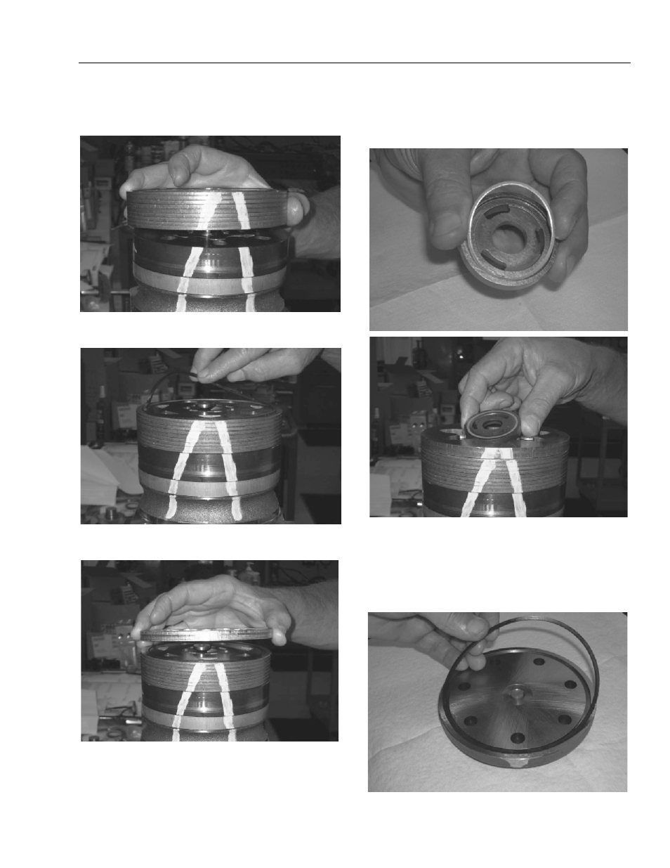
15. Assemble the manifold (7) over the alignment studs
and drive link (10) and onto the rotor set. Be sure the
correct manifold surface is against the rotor set.
16. Apply grease to a new seal ring (4) and insert it in
the seal ring groove exposed on the manifold.
17. Assemble the commutator ring (6) over alignment
studs onto the manifold.
18. Assemble a new seal ring (3) flat side up, into com-
mutator (5) and assemble commutator over the end
of drive link (10) onto manifold (7) with seal ring side
up.
19. Assemble a new seal ring (4) into end cover (2) and
assemble end cover over the alignment studs and
onto the commutator set. If the end cover has only 5
bolt holes be sure the cover holes are aligned with
the 5 threaded holes in housing (18). The correct 5
bolt end cover bolt hole relationship to housing port
bosses is shown below.