To connect the jlg control system analyzer, To connect the jlg control system analyzer -2, Control module location -2 – JLG M400 Service Manual Service Manual User Manual
Page 182
SECTION 6 - JLG CONTROL SYSTEM
6-2
– JLG Lift –
3121827
The JLG Control System controller has a built in LED to
indicate any faults. The system stores recent faults which
may be accessed for troubleshooting. Optional equip-
ment includes an hour meter, beacon light, function cut-
out, and ground alarm. These options may be added later
but must be programmed into the motor controller when
installed.
The Control System may be accessed in one of two ways:
Utilizing a custom designed, hand held analyzer (Ana-
lyzer, JLG part no. 1600244 & Cable, JLG part no.
1600633) which will display two lines of information at a
time, by scrolling through the program.
NOTE: Each module has a label with the JLG part number
and a serial number which contains a date code.
The following instructions are for using the hand held ana-
lyzer.
To Connect the JLG Control System Analyzer
1. Connect the four pin end of the cable supplied with
the analyzer, to the motor controller module located
in the platform box or at the power module and con-
nect the remaining end of the cable to the analyzer.
NOTE: The cable has a four pin connector at each end of
the cable; the cable cannot be connected back-
wards.
2. Power up the Control System by turning the lower
key to the platform or ground position and pulling
both emergency stop buttons on.
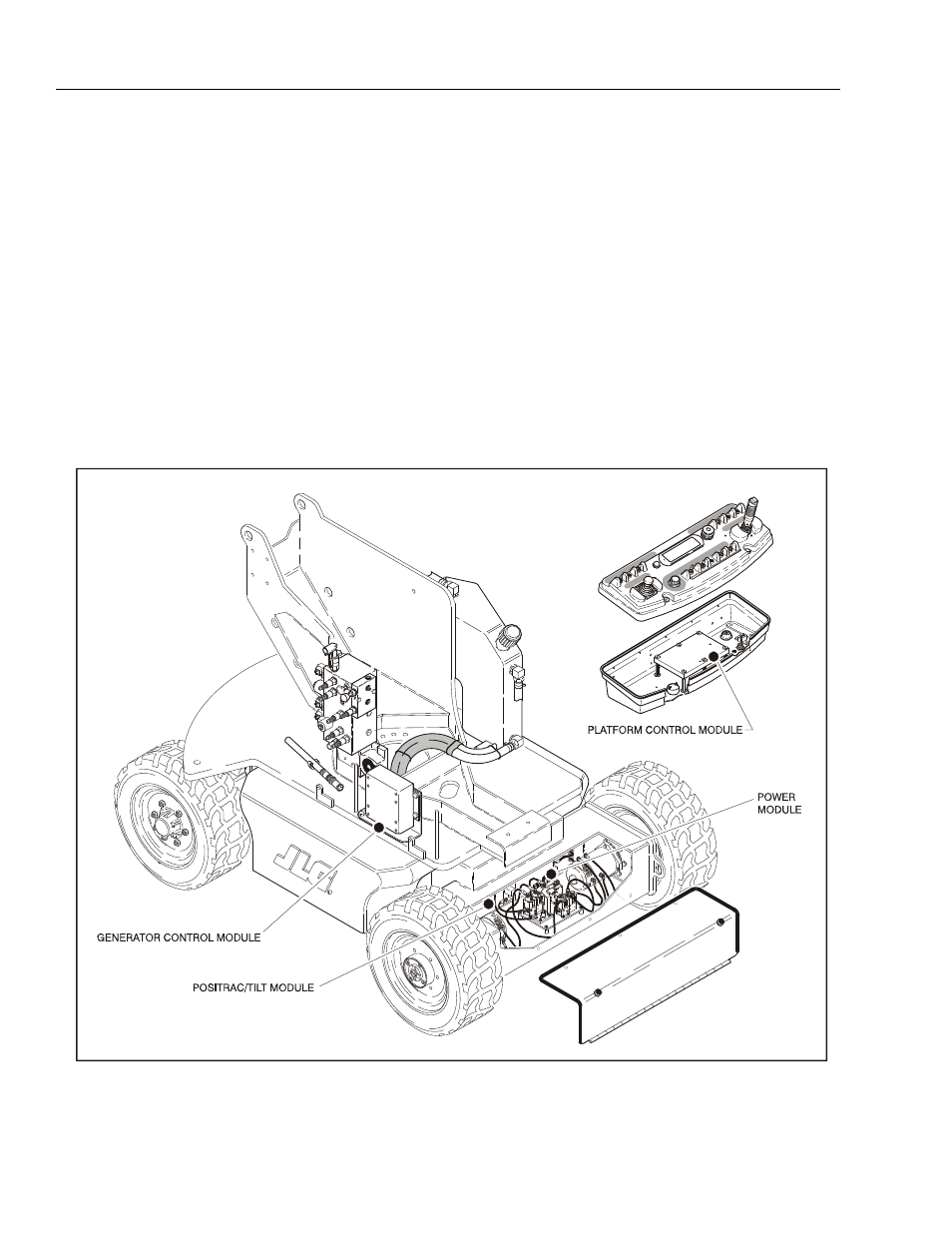
Figure 6-2. Control Module Location