Assembly, 10 footswitch adjustment, 11 boom limit switches – JLG M400 Service Manual Service Manual User Manual
Page 126: Assembly -10, Footswitch adjustment -10, Boom limit switches -10, Platform support torque values -10
SECTION 4 - BOOM & PLATFORM
4-10
– JLG Lift –
3121827
Assembly
NOTE: For location of components See Section 4-7., Loca-
tion of Components - Articulating Jib Boom.
1. Align lift cylinder, rotator support top tube holes, and
top tubes. Using a soft head mallet, install cylinder
pin #6 into articulating jib boom and secure with
mounting hardware.
2. Align bottom tubes with attach holes in rotator sup-
port. Using a soft head mallet, install rotator support
pin #5 into articulating jib boom and secure with
mounting hardware.
3. Align articulating jib boom with attach hole in articu-
lating jib boom pivot weldment. Using a soft head
mallet, install rotator support pin #4 into articulating
jib boom and secure with mounting hardware.
4. Align bottom tubes with attach holes in articulating
jib boom pivot weldment. Using a soft head mallet,
install rotator support pin #3 into articulating jib
boom pivot weldment and secure with mounting
hardware.
5. Align articulating jib boom pivot weldment with
attach holes in fly boom assembly. Using a soft head
mallet, install pivot pin #2 into fly boom assembly
and secure with mounting hardware.
6. Align the slave leveling cylinder with attach holes in
articulating jib boom pivot weldment. Using a soft
head mallet, install slave leveling cylinder pin #1
into articulating jib boom pivot weldment and secure
with mounting hardware.
4.10 FOOTSWITCH ADJUSTMENT
Adjust switch so that functions will operate when pedal is
at center of travel. If switch operates within last 1/4 inch
(6.35 mm) of travel, top or bottom, it should be adjusted.
4.11 BOOM LIMIT SWITCHES
Refer to Figure 4-10., Boom Limit Switches for adjust-
ments to be made to the two Boom Limit Switches which
bolt in place on the upright.
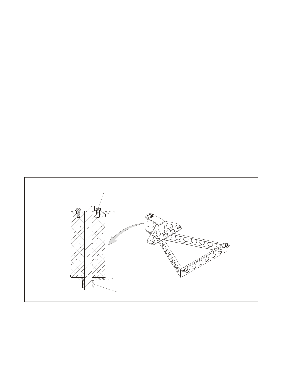
A,B,D
C,D
A
B
C
D
Torque to 50 ft.lbs. (68 Nm)
Loctite #242
Torque 250-270 ft. lbs. (339-366 Nm)
Check torque every 150 hours of operation
Figure 4-9. Platform Support Torque Values
NOTE: If any rotator bolts are replaced, all bolts
on the rotator should be retorqued.