Sample capacity chart (aus), Sample capacity chart (aus) -7, Warning – JLG 2505H Operator Manual User Manual
Page 83
Section 5 - Attachments and Hitches
5-7
31200743
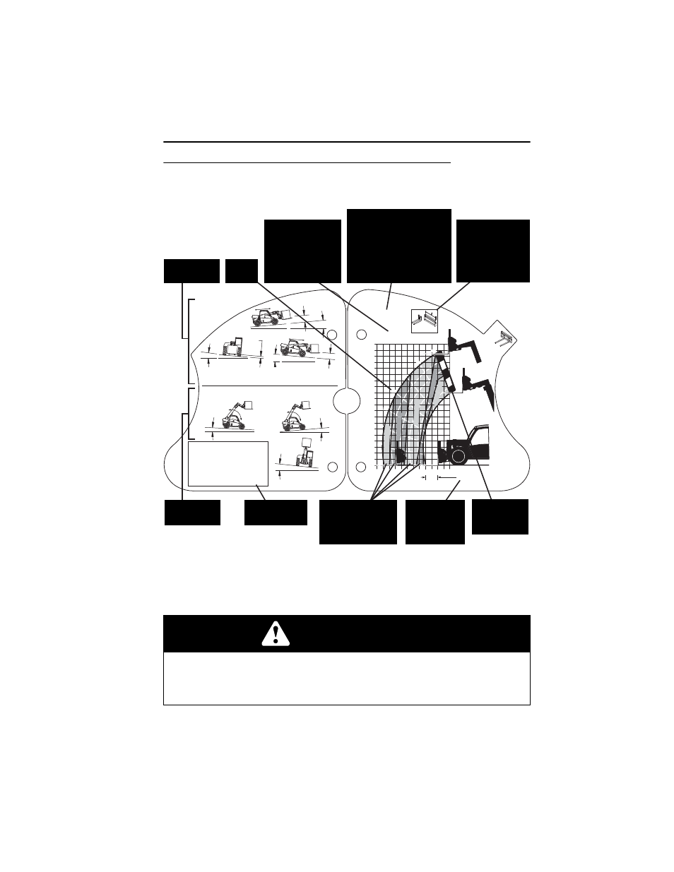
Sample Capacity Chart (AUS)
Note: This is a sample capacity chart only! DO NOT use this chart, use the one
located in your operator cab.
WARNING
TIP OVER HAZARD. All loads shown on rated capacity chart are based on
machine being on firm ground with frame level (see page 4-5); the forks being
positioned evenly on carriage; the load being centered on forks; proper size tires
being properly inflated; and the telehandler being in good operating condition.
OAL2150
XX
XX
XX
XX
XX
XX
XX
XX
XX
XX
X
XX XX XX XX XX XX XX
XX
XXXX XXXX
0°
10°
20°
30°
40°
50°
60°
70°
B
D
A
C
E
1
XX
+
= XXX XX MAX
XXXX
XXXX XX
XXXX XX
XXXX XX
XXXX XX
XXXX XX
XXX
XXXXXXXXXX
X° MAX
XXXMM
MAX
XXXMM MAX
X° MAX
XXXMM MAX
X° MAX
X° MAX
X° MAX
X° MAX
TRAVELING (PICK & CARRY)
REQUIRES FIRM SURFACE WITH LOAD ON FORKS.
MAX TRAVEL SPEED XXKM/H. BOOM FULLY RETRACTED.
LIFTING (STATIONARY)
REQUIRES FIRM SURFACE WITH LOAD ON FORKS.
SPECIFICATIONS FOR SAFE USE
1. TIRE SIZES: (XX XX, XXXXX)
2. TIRE PRESSURE: (XXXX XX)
3. IN-SERVICE WIND SPEED: (XXM/S, XXKM/H)
4. GROUND CONDITIONS:
- FIRM SURFACES FOR BOTH LIFTING
AND TRAVELING.
- SLOPE AND LOAD LISTED ABOVE FOR
BOTH CONFIGURATIONS.
5. STANDARD USED: (XX XXXXXXXX).
This Capacity Chart may be
used with this model ONLY.
The telehandler model is
indicated on the boom or
chassis. Model XXXX is
used for demonstration
purposes only.
Boom
Extension
Indicator (arc)
Load zones indicate
the maximum
weight that may be
safely lifted.
Load center
must be equal
to or less than
value shown.
Attachment type,
weight and
dimensions must
be equal to or less
than the data
shown.
Specifications
For Safe Use
Lifting
Information
Traveling
Information
Boom
Angle
Quick Attach Type
Blank = Standard
Quick Attach
UQC = Universal
Quick Attach