5 use of the capacity chart, Capacity indicator locations, 5 use of the capacity chart -5 – JLG 2505H Operator Manual User Manual
Page 81: Capacity indicator locations -5
Section 5 - Attachments and Hitches
5-5
31200743
5.5
USE OF THE CAPACITY CHART
To properly use the capacity chart (see page 5-6), the operator must first determine
and/or have the following:
1. An approved attachment. See “Approved Attachments” on page 5-1.
2. The proper Capacity Chart(s).
3. Weight of the load being lifted.
4. Load placement information:
a. HEIGHT where the load is to be placed.
b. DISTANCE from the front tires of the telehandler to where the load is to be
placed.
5. On the capacity chart, find the line for the height and follow it over to the
distance.
6. The number in the load zone where the two cross is the maximum capacity for
this lift. If the two cross at a division between zones, the smaller number must
be used.
The number in the load zone must be equal to or greater than the weight of the load
to be lifted. Determine the limits of the load zone on the capacity chart and keep
within these limits.
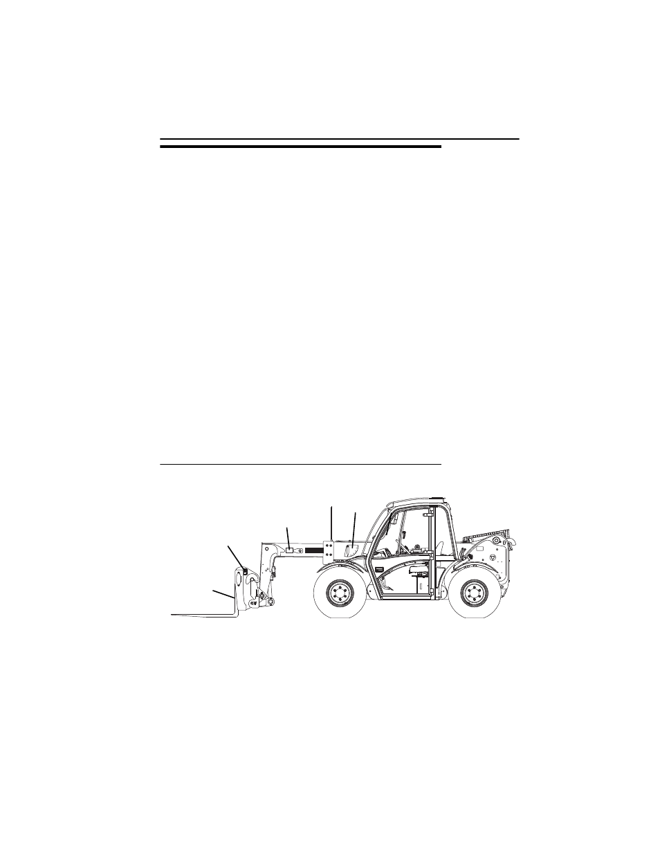
Capacity Indicator Locations
OAL1730
B
A
-10 1020 30
40 50
60 70
80
BOOM
EXTENSION
INDICATOR
BOOM
ANGLE
INDICATOR
ATTACHMENT
IDENTIFICATION
PLATE
FORK
WEIGHT
STAMP