8 foot switch adjustment, Foot switch adjustment -19, Control card -19 – JLG 601S Service Manual User Manual
Page 149: Flow control card settings -19, Flow control card ramp time -19, Function speeds -19
SECTION 4 - BOOM & PLATFORM
3120866
– JLG Lift –
4-19
2. Rotating the adjustment potentiometer clockwise
will increase the ramp time.
4.8 FOOT SWITCH ADJUSTMENT
Adjust so that functions will operate when pedal is at cen-
ter of travel. If switch operates within last 1/4 in. (6.35 mm)
of travel, top or bottom, it should be adjusted.
Table 4-1. Flow Control Card Settings
Function
Minimum Current
Maximum Current
Lift Up
450 to 55o mA
1400 to 1500 mA
Lift Down
450 to 550 mA
1400 to 1500 mA
Swing Right
450 to 550 mA
1400 to 1500 mA
Swing Left
450 to 550 mA
1400 to 1500 mA
Flow Control
750 to 850 mA
450 to 550 mA
Drive Forward
40 to 60 mA
150 to 200 mA
Drive Reverse
40 to 60 mA
150 to 200 mA
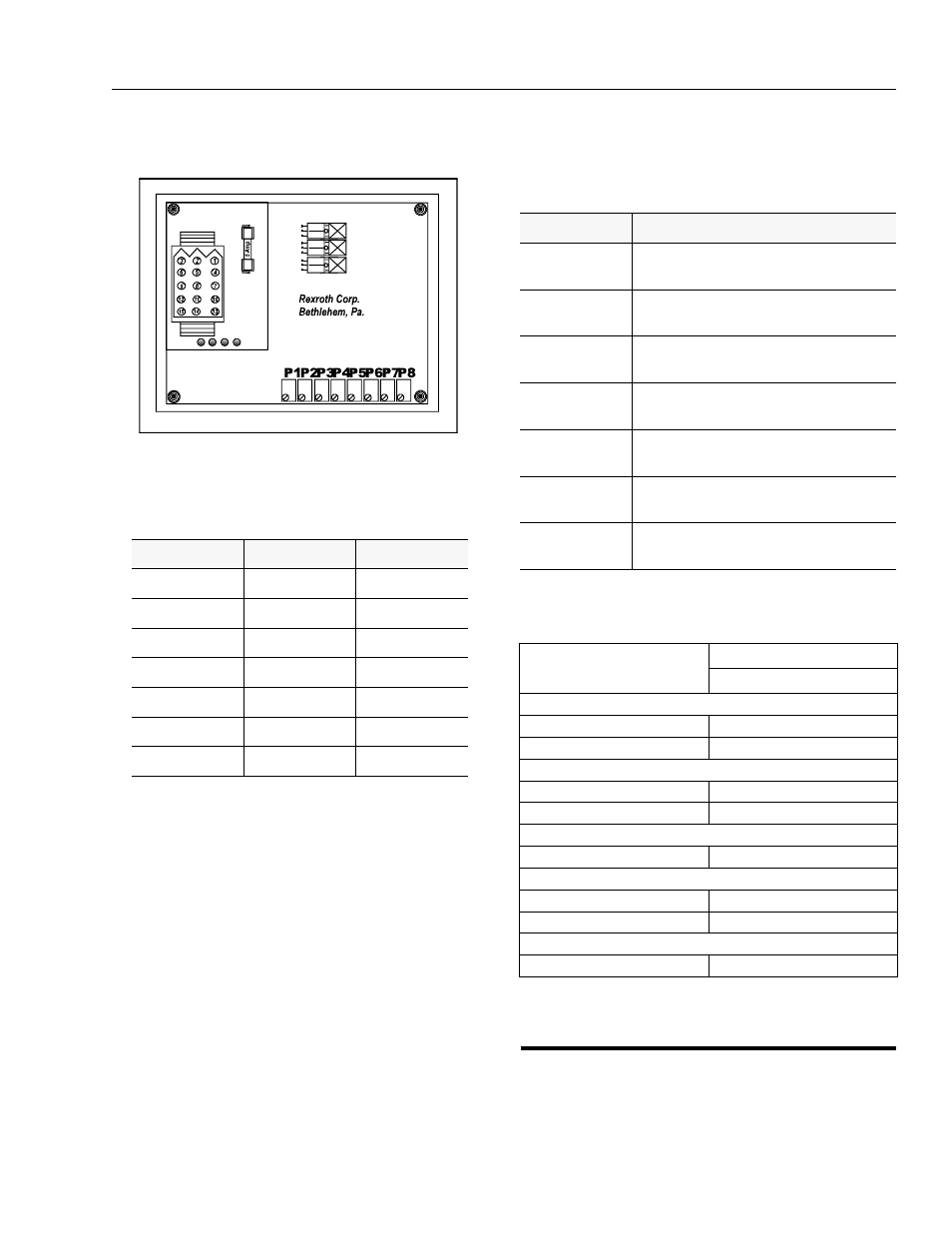
Figure 4-26. Control Card
Table 4-2. Flow Control Card Ramp Time
Function
Ramp Time
Lift Up
Ramp Up Time = 4:00 sec.
Ramp Down Time = 3:00 sec.
Lift Down
Ramp Up Time = 4:00 sec.
Ramp Down Time = 3:00 sec.
Swing Right
Ramp Up Time = 4:00 sec.
Ramp Down Time = 3:00 sec.
Swing Left
Ramp Up Time = 4:00 sec.
Ramp Down Time = 3:00 sec.
Drive Forward
Ramp Up Time = 4:30 sec.
Ramp Down Time = 2:30 sec.
Drive Reverse
Ramp Up Time = 4:30 sec.
Ramp Down Time = 2:30 sec.
Flow Control
Ramp Up Time = 3:00 sec.
Ramp Down Time = 0:00 sec.
Table 4-3. Function Speeds
Function
Function Speed
In Seconds
Telescope
Extend
48-61
Retract
24-32
Lift
Up
46-60
Down
33-43
Swing Speed
Full 360
79-101
Platform Rotation
Left
22-30
Right
22-30
Drive Speed
32-36 @ 200ft.