11 hydraulic cylinders, Hydraulic cylinders, General cylinder removal instructions – JLG 266 LoPro Service Manual User Manual
Page 89: General cylinder disassembly
8.19
266, 307, 266 LoPro
Hydraulic System
8.11
HYDRAULIC CYLINDERS
8.11.1
General Cylinder Removal
Instructions
1. Park the machine on a firm, level surface, fully
retract the boom, lower the boom, place the
transmission control lever in (N) NEUTRAL, engage
the park brake and shut the engine OFF.
2. Chock the wheels.
3. Place a Do Not Operate Tag on both the ignition key
switch and the steering wheel, stating that the
machine should not be operated.
4. Open the engine cover. Allow the system fluids to
cool.
5. Label, disconnect and cap hydraulic hoses in
relation to the cylinder.
6. Attach a suitable sling to an appropriate lifting device
and to the cylinder. Make sure the device used can
actually support the cylinder.
7. Remove the lock bolt and/or any retaining clips
securing the cylinder pins. Remove the cylinder pins.
8. Remove the cylinder.
9. Wipe up any hydraulic fluid spillage in, on, near or
around the machine.
8.11.2
General Cylinder Disassembly
1. Clean the cylinder with a suitable cleaner before
disassembly. Remove all dirt, debris and grease
from the cylinder.
2. Clamp the barrel end of the cylinder in a soft-jawed
vise or other acceptable holding equipment if
possible.
IMPORTANT: Avoid using excessive force when
clamping the cylinder in a vise. Apply only enough force
to hold the cylinder securely. Excessive force can
damage the cylinder tube.
3. If applicable, remove the counterbalance valve from
the side of the cylinder barrel.
IMPORTANT: DO NOT tamper with or attempt to adjust
the counterbalance valve cartridge. If adjustment is
necessary, replace the counterbalance valve with a new
part.
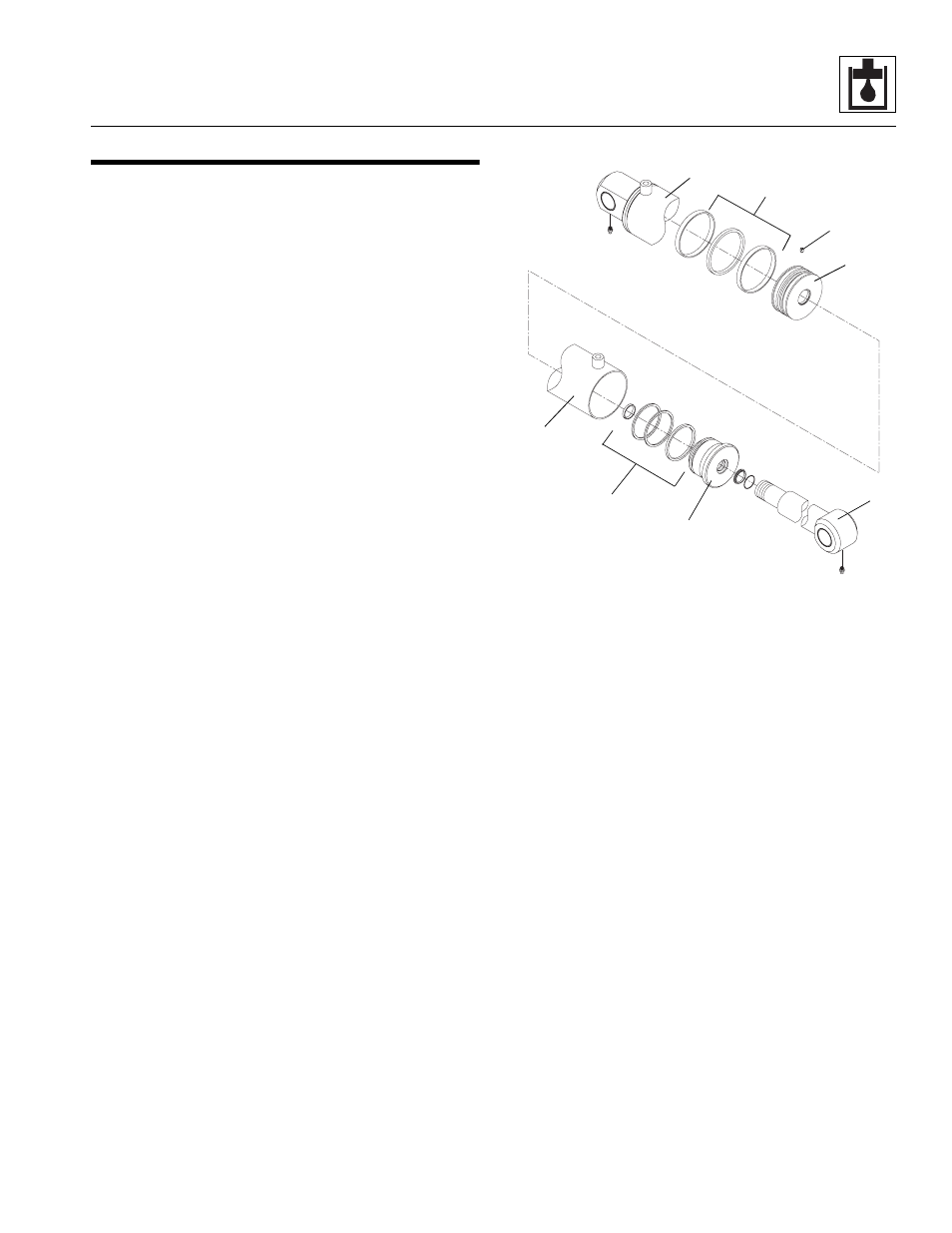
4. Extend the rod (5) to allow access to the base of the
cylinder.
IMPORTANT: Protect the finish on the rod at all times.
Damage to the surface of the rod can cause seal failure.
5. Using a pin spanner wrench, unscrew the head
gland (6) from the barrel (1). A considerable amount
of force will be necessary to remove the head gland.
Carefully slide the head gland down along the rod
toward the rod eye end, away from the cylinder
barrel.
IMPORTANT: When sliding the rod and piston assembly
out of the tube, prevent the threaded end of the tube
from damaging the piston. Keep the rod centered within
the tube to help prevent binding.
6. Carefully pull the rod assembly along with the head
gland out of the cylinder barrel.
7. Fasten the rod end in a soft-jawed vise, and put a
padded support under and near the threaded end of
the rod to help prevent damage to the rod.
8. Remove the set screw (3) from the piston (4).
MAH0160
1
4
3
2
6
5
2
1