Engine disassembly, inspection and service, Engine installation – JLG 266 LoPro Service Manual User Manual
Page 68
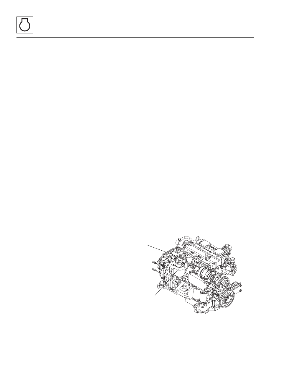
Engine: Deutz BF 4M 2012
7.8
266, 307, 266 LoPro
22. Detach exhaust and air cleaner hoses from the
engine. Cover air inlets to protect from dirt & debris.
23. Remove air cleaner assembly from engine
compartment.
24. Completely disconnect exhaust pipe.
25. Remove the hydraulic reservoir fill tube.
26. Secure the engine with a lifting strap or chain from
the appropriate lifting points (3). Use a suitable hoist
or overhead crane.
27. Remove the 4 motor mount bolts that attach the
engine to the frame.
28. Carefully lift the engine from the machine. Avoid
causing damage to the surrounding parts.
29. Lift the engine clear of the machine, and lower it onto
suitable supports or stand. Secure the engine so
that it will not move or fall.
7.8.2
Engine Disassembly, Inspection and
Service
Engine disassembly, internal inspection, service, repair
and assembly procedures are covered in the Deutz BF
4M 2012 service manual. Several special engine service
tools are required to properly service the Deutz engine.
Contact your local Deutz AG Service partner for further
information.
Note: If the engine is being replaced, there may be external
components that will be required to be transferred from the
original engine to the replacement engine depending upon
who you purchase the new engine from and the
configuration of your replacement engine. Refer to the
appropriate Deutz user manual for detailed procedures that
cover the transfer of original engine components to the
replacement engine.
7.8.3
Engine Installation
Note: Refer to Section 2.2, “Torques,” for specific
fastener torque specifications.
1. Position engine in engine compartment being sure to
line up the 4 motor mount holes. Replace bolts and
torque to 97 Nm (71 lb-ft).
2. Connect the hydraulic reservoir fill tube.
3. Connect the exhaust pipe to the engine.
4. Install the air cleaner assembly into the engine
compartment and attach hose to air intake.
5. Reconnect throttle cable (2) onto the engine, if
necessary adjust for full travel.
6. Feed engine harness wires through the engine
compartment wall and plug into the ports located on
the side of the cab.
7. Reattach the relay distribution panel and connect
any loose wires.
8. Install the overflow bottle bracket and secure the
expansion tank.
9. Attach the engine fan.
10. Secure the radiator with the necessary bolts and
attach the fan safety shroud. Check that the fan top
clearance is adequate with regard to the radiator.
Reattach the previously labeled hoses. Refer to
Section 7.4.2, “Radiator/Oil Cooler and Coolant
Heater Replacement.” Fill with a 50/50 mixture of
ethylene glycol and water.
11. Install the filter bracket assembly. Secure the
hydraulic and fuel filters and windshield washer fluid
reservoir.
12. Connect the fuel inlet line to the fuel filter (1) and
reconnect the return fuel line to the engine.
Note: If the Non-Return Fuel Valve is not installed on
the fuel return line, refer to Section 7.6.2, “Non-Return
Fuel Valve.”
13. Uncap and reconnect all hydraulic hoses and fittings
to the engine and necessary hydraulic elements.
Keep hoses free of dirt & debris.
14. Refill the hydraulic reservoir (Refer to the
appropriate Operator & Safety Manual for
information concerning the hydraulic oil and filter
change).
15. Replace the battery tray and battery and reconnect
the battery terminals, being sure to start with the
positive (+) terminal.
MAH0620
1
2