12 controller, Controller, Main control valve solenoids – JLG 266 LoPro Service Manual User Manual
Page 117: Load moment indicator setting, Joystick functionality setting, Warning
9.25
266, 307, 266 LoPro
Electrical System
9.11.8
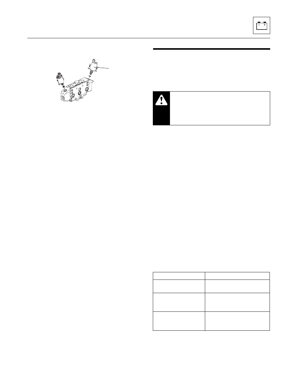
Main Control Valve Solenoids
a. Main Control Valve Solenoid Removal
1. Open the engine cover. Allow the engine to cool.
2. Disconnect the battery negative (-) cable at the
battery negative (-) terminal.
3. Disconnect the wiring connector at the valve
solenoid lead.
4. Loosen and remove the two allenhead mounting
screws.
5. Remove the valve solenoid (4) being careful not to
lose or damage any o-rings. Note the location of any
orifices, check valves and o-rings if equipped.
b. DO NOT disassemble a valve solenoid. Replace a
defective valve solenoid with a new solenoid.
c. Main Control Valve Solenoid Installation
1. Install the valve solenoid using new o-rings and
tighten the allenhead screws. Do not over tighten.
2. Connect the wire connector to the valve solenoid.
3. Start the machine and slowly move joystick to
engage function. If further troubleshooting is
required, refer to Section 9.4, “Electrical System
Schematics.” or Section 8.6, “Hydraulic Schematic.”
4. Close and secure the engine cover.
9.12
CONTROLLER
If the controller has been replaced, the default settings for
the Load Moment Indicator and the Joystick functions
must be properly configured.
9.12.1
Load Moment Indicator Setting
1. Connect the JLG Analyzer (P/N 2901443) tool to the
PCB board on the machine. Turn the ignition to the
ON position.
2. Scroll through the menus to find "ACCESS LEVEL 2"
3. Press enter and key in the code "38644" to enter
"ACCESS LEVEL 0".
4. Scroll through the menus to find "MACHINE SETUP"
5. Select "LMI ASIGNMENT: 2-CUTOUT"
6. Confirm settings and remove the analyzer.
7. Verify the LMI is functioning correctly. Refer to the
appropriate Operation & Safety Manual.
9.12.2
Joystick Functionality Setting
1. Connect the JLG Analyzer (P/N 2901443) tool to the
machine.
2. Scroll through the menus to find "ACCESS LEVEL 2"
3. Press enter and key in the code "38644" to enter
"ACCESS LEVEL 0".
4. Scroll through the menus to find "MACHINE SETUP"
5. Choose the option that coincides with the joystick
decal in the cab.
6. Verify that joystick functions coincide with the
joystick decal in the cab.
MAH1080
4
WARNING:
The Load Moment
Indicator (LMI) must be set to remain active
with the machine. Without a functioning LMI, a
potentionally dangerous situation may occur
resulting in serious injury or death.
Code
Function
JYSTK ASSIGN:
1-X/K FORK/TELE
Joystick left/right = fork tilt
Knurl = boom extend/retract
JYSTK ASSIGN:
2-X/KS TELE/FORK
Joystick left/right = boom
extend/retract
Knurl = fork tilt (slow)
JYSTK ASSIGN:
3-X/KF TELE/FORK
Joystick left/right = boom
extend/retract
Knurl = fork tilt (fast)