JLG 3246E2 ANSI Operator Manual User Manual
Page 53
SECTION 4 - MACHINE OPERATION
3120736
– JLG Lift –
4-3
NOTE: If the machine is equipped with a footswitch (Japa-
nese Specification Only), the footswitch must be
depressed in conjunction with the red trigger switch,
located on the joystick. Power is removed from the
platform controls when the footswitch is released.
3.
If operating from the ground controls, position the lift
switch to up and hold until desired elevation is
achieved. If operating from the platform controls,
press and hold the enable switch, move the lift
switch forward (up) and hold until desired elevation
is reached. The lift switch works in conjunction with
the enable switch.
Lowering
ENSURE SCISSOR ARM AREA IS FREE OF PERSONNEL PRIOR
TO LOWERING PLATFORM.
NOTE: The machine i s equipped with a decent alarm which
will sound as the machine is being lowered.
If operating from the ground controls, position the lift
switch to down and hold until desired elevation is
achieved or until platform is fully lowered. If operating
from the platform controls, press the enable switch and
push the lift switch backward (down) and hold until
desired elevation is reached or until platform is fully low-
ered. The lift switch works in conjunction with the enable
switch.
DO NOT ‘LIFT DOWN’ WITHOUT COMPLETELY RETRACTING THE
PLATFORM EXTENSION.
4.5
PLATFORM EXTENSION
Manual Platform Extension
The machine is equipped with a mechanically extendible
deck, which adds 3 ft (0.9 m) to the front of the platform,
giving the operator better access to worksites. To extend
the deck, pull the plunger pin, attached to lanyards,
located at the right side of the platform extension, extend
platform extension and release the pin so that it locks in
the front hole in the rail. Do not drive machine unless plat-
form extension is properly pinned. To retract the deck,
remove pin, pull platform extension back in and install pin
back into rear hole. Do not drive machine unless platform
extension is properly pinned. Maximum capacity of the
deck extension is 250 lb (120 kg) - 1 person.
4.6
STEERING
To steer the machine, the thumb operated steer control
switch on the joystick is positioned to the right for traveling
right, or to the left for traveling left. When released, the
switch will return to the center-off position and the wheels
will remain in the previously selected position. To return
the wheels to the straightened position, the switch must
be activated in the opposite direction until the wheels are
centered.
4.7
TRAVELING (DRIVING)
NOTE: High drive is cut out when the platform is raised
above the following preset heights:
D O N O T D R I V E W I T H P LATF OR M R A I S E D E X C E P T ON A
SMOOTH, FIRM AND LEVEL SURFACE FREE OF OBSTRUCTIONS
AND HOLES.
TO AVOID LOSS OF TRAVEL CONTROL OR UPSET ON GRADES
AND SIDESLOPES, ON 1532E2 AND 1932E2 DO NOT DRIVE
MACHINE ON GRADES EXCEEDING 20%. ON 2032E2/2632E2/
2646E2/3246E2 DO NOT DRIVE MACHINE ON GRADES EXCEED-
ING 25%.
TRAVEL GRADES IN “LOW” DRIVE SPEED ONLY. USE EXTREME
CAUTION WHEN DRIVING IN REVERSE AND AT ALL TIMES WHEN
DRIVING WITH PLATFORM ELEVATED AND ESPECIALLY WHEN
DRIVING WITH ANY PART OF MACHINE WITHIN 6 FEET (1.8
METERS) OF AN OBSTRUCTION.
TO GO BACK DOWN THE GRADE, IF TRAVELING FORWARD UP
T H E G R A D E , B U M P T H E C O N T R O L H A N D L E F O RWA R D
SLIGHTLY TO ENSURE THE BRAKES ARE RELEASED BEFORE
DESCENDING THE GRADE
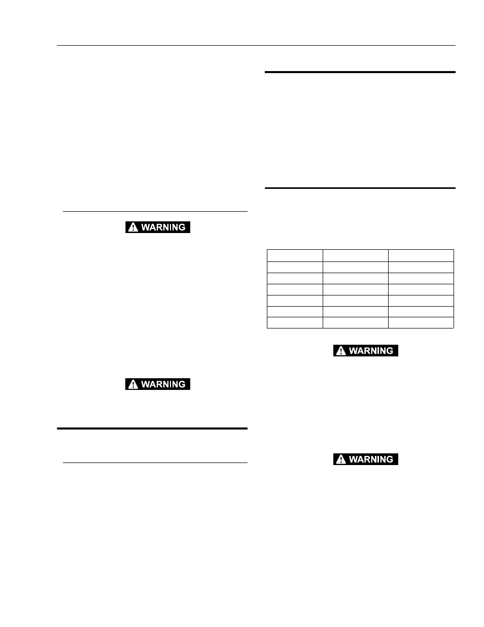
Table 4-2. High Drive Cutout
Model
In
m
1532E2
46 - 55
1.2 - 1.4
1932E2
48 - 60
1.2 - 1.5
2032E2
84
2.1
2646E2
102
2.6
2632E2
114
2.9
3246E2
60 - 65
1.5 - 1.7