JLG 3246E2 ANSI Operator Manual User Manual
Page 52
SECTION 4 - MACHINE OPERATION
4-2
– JLG Lift –
3120736
4.2
GENERAL
This section provides the necessary information needed
to operate the machine. Included in this section are the
procedures for starting, stopping, traveling, steering, park-
ing, platform loading and transporting the machine. It is
important that the user read and understand the proper
procedures before operating the machine.
4.3
MOTOR OPERATION
Power Selector Switch
The power selector switch functions to direct battery
power to the desired control station. With the switch in the
ground position, battery power is supplied to the emer-
gency stop switch at the ground control station. When the
switch is in the platform position, battery power is sup-
plied to the emergency stop switch at the platform control
station. The power selector switch should be in the off
position when recharging the batteries and/or parking the
machine overnight.
Emergency Stop Switch
This switch, when in the on (out) position, provides battery
power to the ground controls or platform controls, as
applicable. In addition, the switch can be used to turn off
power (push the switch in) to the function controls in the
event of an emergency.
NOTE: If the machine is equipped with a footswitch (Japa-
nese Specification Only), the footswitch must be
depressed in conjunction with the red trigger switch,
located on the joystick. Power is removed from the
platform controls when the footswitch is released.
Motor Activation
With the power selector switch in the appropriate position
(platform or ground) and the applicable emergency stop
switch in the on position and a function switch or control-
ler is operated and held, the motor becomes activated
and operates the desired function. When operating from
the ground controls, the power selector switch must be
held in the ground position while the function is being
operated. When operating the platform controls, the lift
switch must be used in conjunction with the enable
switch, to drive the lever must be depressed in conjunc-
tion with the joystick travel.
IF A MOTOR MALFUNCTION NECESSITATES UNSCHEDULED
SHUTDOWN, DETERMINE AND CORRECT CAUSE BEFORE
RESUMING ANY OPERATION.
ALWAYS POSITION POWER SELECTOR AND EMERGENCY STOP
SWITCHES TO THE ‘OFF’ POSITION WHEN MACHINE IS NOT IN
USE.
4.4
RAISING AND LOWERING (LIFTING)
DO NOT RAISE PLATFORM EXCEPT ON A HARD, LEVEL SUR-
FACE FREE OF OBSTRUCTIONS AND HOLES.
NOTE: The lift switch will not operate if the red trigger switch
on the joystick is depressed.
Raising
1.
If the machine is shut down, place the power selec-
tor switch to the desired position (platform or
ground).
2.
Position the applicable emergency stop switch to
the on position.
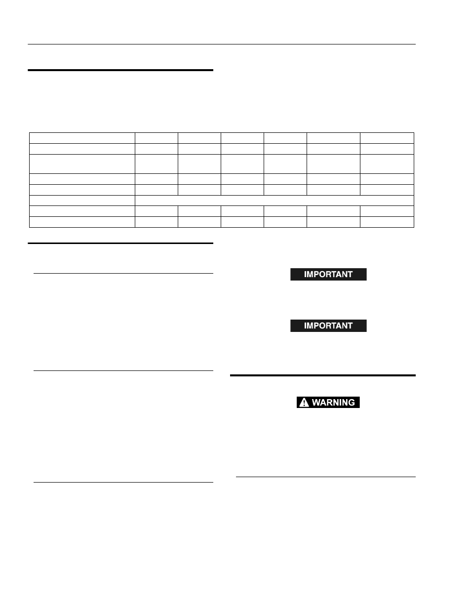
Table 4-1. Operating Specificatoins
Model
1532E2
1932E2
2032E2
2632E2
2646E2
3246E2
Maximum Occupants
2
2
2
2
2
2
Maximum Workload (Capacity)
Extension Only:
600 lb
250 lb
500 lb
250 lb
750 lb
250 lb
500 lb
250 lb
750 lb
250 lb
700 lb
250 lb
Maximum Travel Grade (Gradeability):
20%
20%
25%
25%
25%
25%
Maximum Platform Height:
15 ft
19 ft
20 ft
26 ft
26ft
32ft
Maximum Tire Load
Reference Decal on Machine
Maximum Drive Speed
2.5 mph
2.5 mph
2.5 mph
2.0 mph
2.0 mph
2.0 mph
Gross Machine Weight
2925 lb
3000 lb
3910 lb
5325 lb
4325 lb
6100 lb