Cylinder piston nut torque specifications -16, Holding valve torque specifications -16 – JLG 120HX Service Manual User Manual
Page 38
SECTION 2 - PROCEDURES
2-16
– JLG Lift –
3120819
NOTE: Self-locking setscrews used on piston nuts should be
discarded and replaced whenever they are removed.
8.
If applicable, install the setscrew(s) which secure the
piston attaching nut to the diameter groove.
9.
Remove the cylinder rod from the holding fixture.
10.
Place new o-rings and seals in the applicable out-
side diameter grooves of both the piston and the cyl-
inder head.
11.
Position the cylinder barrel in a suitable holding fix-
ture.
EXTREME CARE SHOULD BE TAKEN WHEN INSTALLING THE
CYLINDER ROD, HEAD, AND PISTON. AVOID PULLING THE ROD
OFF-CENTER, WHICH COULD CAUSE DAMAGE TO THE PISTON
AND CYLINDER BARREL SURFACES.
12.
With barrel clamped securely, and while adequately
supporting the rod, insert the piston end into the
barrel cylinder. Ensure that the piston loading o-ring
and seal ring are not damaged or dislodged.
13.
Continue pushing the rod into the barrel until the cyl-
inder head gland can be inserted into the barrel cyl-
inder or, if applicable, until the cylinder head threads
engage the threads of the barrel.
14.
If applicable, secure the cylinder head retainer using
a suitable spanner type wrench in the holes pro-
vided.
15.
After the cylinder has been reassembled, the rod
should be pushed all the way in (fully retracted) prior
to the reinstallation of any holding valve or valves.
16.
If applicable, install the cartridge-type holding valve
and fittings in the rod port block using new o-rings
as applicable.
IF THE CYLINDER IS TO BE TESTED PRIOR TO INSTALLATION ON
THE MACHINE, EXTREME CARE SHOULD BE USED TO INSURE
THAT THE OUTER END OF THE ROD IS SUPPORTED. USE
EITHER A TRAVELING OVERHEAD HOIST, FORKLIFT, OR OTHER
MEANS TO SUPPORT THE OVERHANGING WEIGHT OF THE
EXTENDING ROD.
NOTE: Steps (17) through (20) apply to the telescope cylin-
der.
17.
Elevate the barrel end of the cylinder to a work
bench or other suitable device.
18.
Plug the retract port and supply hydraulic power to
the extend port.
19.
Open the bleeder port plug (TP), venting all trapped
air to atmosphere. Retighten the bleeder port plug.
Disconnect the hydraulic power source and remove
plug from retract port.
20.
An alternative to steps (18) through (20) is to posi-
tion the barrel horizontally in a suitable holding
device, attach a hydraulic power source to both
extend and retract ports, while supporting the cylin-
der rod, cycle the cylinder a minimum of 5 times with
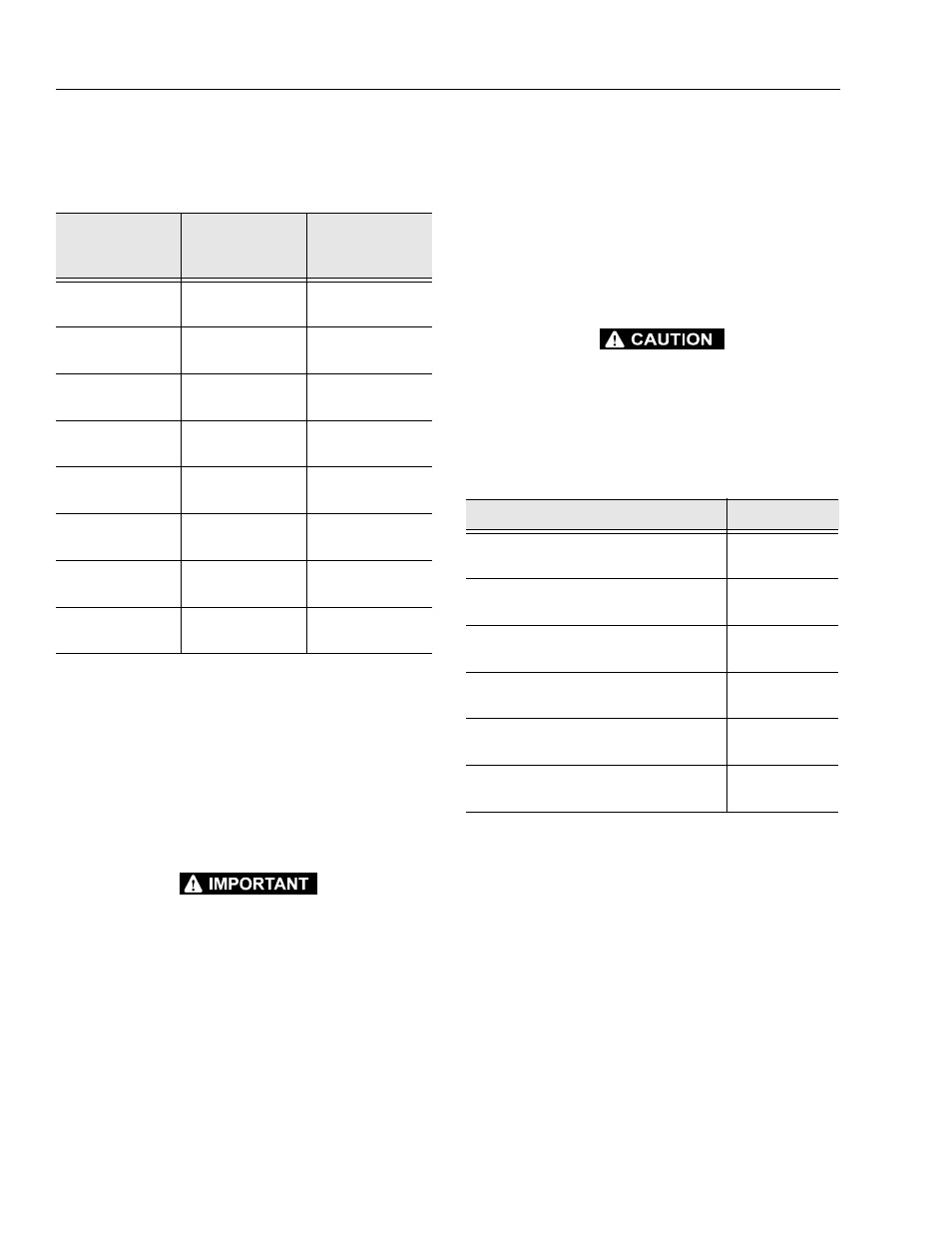
Table 2-2. Cylinder Piston Nut Torque Specifications
Description
Nut Torque
Value (w/Loctite)
Setscrew
Torque Value (w/
Loctite)
Axle Extension
Cylinder
542 Nm (400 ft.
lb.)
11 Nm (100 in.
lb.)
Extend-a-Reach
Cylinder
542 Nm (400 ft.
lb. )
11 Nm (100 in.
lb.)
Frame Jack
Cylinder
542 Nm (400 ft.
lb.)
11 Nm (100 in.
lb.)
Level/Slave
Cylinder
271 Nm (200 ft.
lb.)
11 Nm
(100 in. lb.)
Lift Cylinder
813 Nm (600 ft.
lb.)
22 Nm (200 in.
lb.)
Master Cylinder
108 Nm (80 ft. lb.)
11 Nm (100 in.
lb.)
Steer Cylinder
108 Nm (80 ft. lb.)
11 Nm (100 in.
lb.)
Telescope
Cylinder
813 Nm (600 ft.
lb.)
22 Nm (200 in.
lb.)
Table 2-3. Holding Valve Torque Specifications
Description
Torque Value
Sun - 7/8 hex M20 x 1.5 thds
41-48 Nm
(30-35 ft. lb.)
Sun - 1-1/8 hex 1-14 UNS thds
61-68 Nm
(45-50 ft. lb.)
Sun - 1-1/4 hex M36 x 2 thds
204-217 Nm
(150-160 ft. lb.)
Racine - 1-1/8 hex 1-1/16 - 12 thds
68-75 Nm
(50-55 ft. lb.)
Racine - 1-3/8 hex 1-3/16 - 12 thds
102-109 Nm
(75-80 ft. lb.)
Racine - 1-7/8 hex 1-5/8 - 12 thds
136-149 Nm
(100-110 ft. lb.)