Operation, Servswitch™ brand fiber kvm extenders – Black Box ACS235A User Manual
Page 89
38
SERVSWITCH™ BRAND FIBER KVM EXTENDERS
6. Operation
The ServSwitch™ Brand Fiber KVM Extender Modules should begin operating as
soon as they (and all attached devices) are plugged in; the green and red Power
LEDs on the units’ rear panels should light. (If either LED on a Module fails to
light, that Module has had an internal failure; contact Black Box Technical
Support as described in Section 7.2.) While the Extender is ON, the Remote
Module’s 7-segment display will continuously indicate system status; see
Section 6.1
for how to interpret the various characters you might see on this
display. If the color of the picture on your remote monitor doesn’t look right, see
Section 6.2
for suggestions on how to fix it.
6.1 Interpreting the Remote Module’s 7-Segment Display
Here are the various indications you might see on the Remote Module’s display,
along with what they mean. The numbers “0” through “3” and the blinking dot will
only appear when AGC is enabled (see Sections 3.2.2 and 3.3.2 or 4.1.3 and 4.2.1).
If more than one error has occurred, all of the corresponding error codes are
displayed in a repeating sequence, one each second.
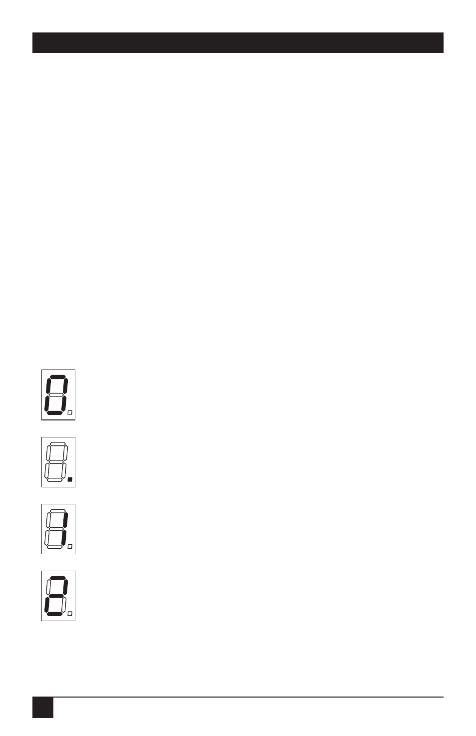
Zero (AGC enabled only): The “OK” display. No trouble; AGC is not
currently active.
Blinking dot (AGC enabled only): The unit is applying AGC to the video
signal, which is normal, and everything else is OK.
One (AGC enabled only): Low red. Even applying max AGC, the unit
can’t equalize the color signals, of which red is at the lowest level.
There’s trouble with the red transmit diode, fiber, or receive diode.
Two (AGC enabled only): Low green. Even applying max AGC, the unit
can’t equalize the color signals, of which green is at the lowest level.
There’s trouble with the green transmit diode, fiber, or receive diode.