Appendix a: pinouts, A.1 connectors on both models – Black Box ACS235A User Manual
Page 44
43
Appendix A: Pinouts
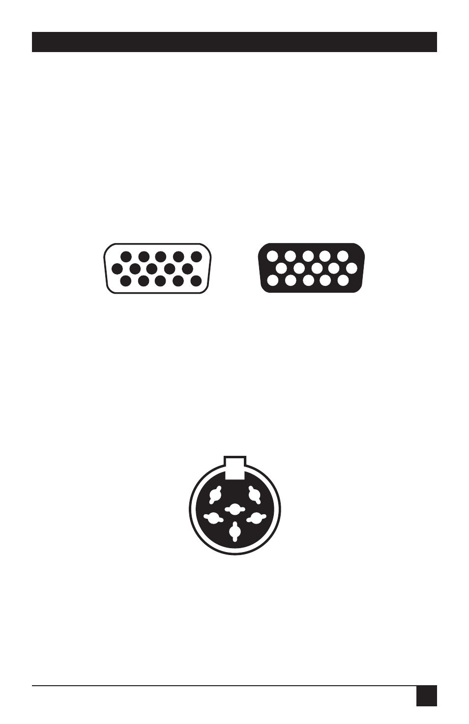
Here are the pinouts for the ServSwitch™ Brand Fiber KVM Extender’s device and
power connectors.
A.1 Connectors on Both Models
A.1.1 T
HE
VGA V
IDEO
C
ONNECTORS
Pin
Signal
Pin
Signal
1
Red
8
Blue Ground
2
Green
10
Sync Ground
3
Blue
13
Horizontal Sync (HSYNC)
6
Red Ground
14
Vertical Sync (VSYNC)
7
Green Ground
(Other pins are not used or not connected.)
A.1.2 T
HE
P
OWER
C
ONNECTOR
Pin
Signal
Shell
Shield
1
Ground
2
+12 VDC
3
Ground
(Other pins are not connected.)
On Remote Module
(HD15 female)
1
5
6
6
10
11
15
15
11
10
5
1
On Local Module
(HD15 male)
APPENDIX A: Pinouts
1
5
6
3
4
2
On Local and
Remote
Modules
(6-Pin DIN
Female)
This manual is related to the following products: