Chapter 3: configuring the acs235a, Figure 3-2. setting the vga/rgb jumpers – Black Box ACS235A User Manual
Page 18
17
CHAPTER 3: Configuring the ACS235A
3.2.1 T
HE
VGA/RGB J
UMPERS
(JP6, JP10,
AND
JP11)
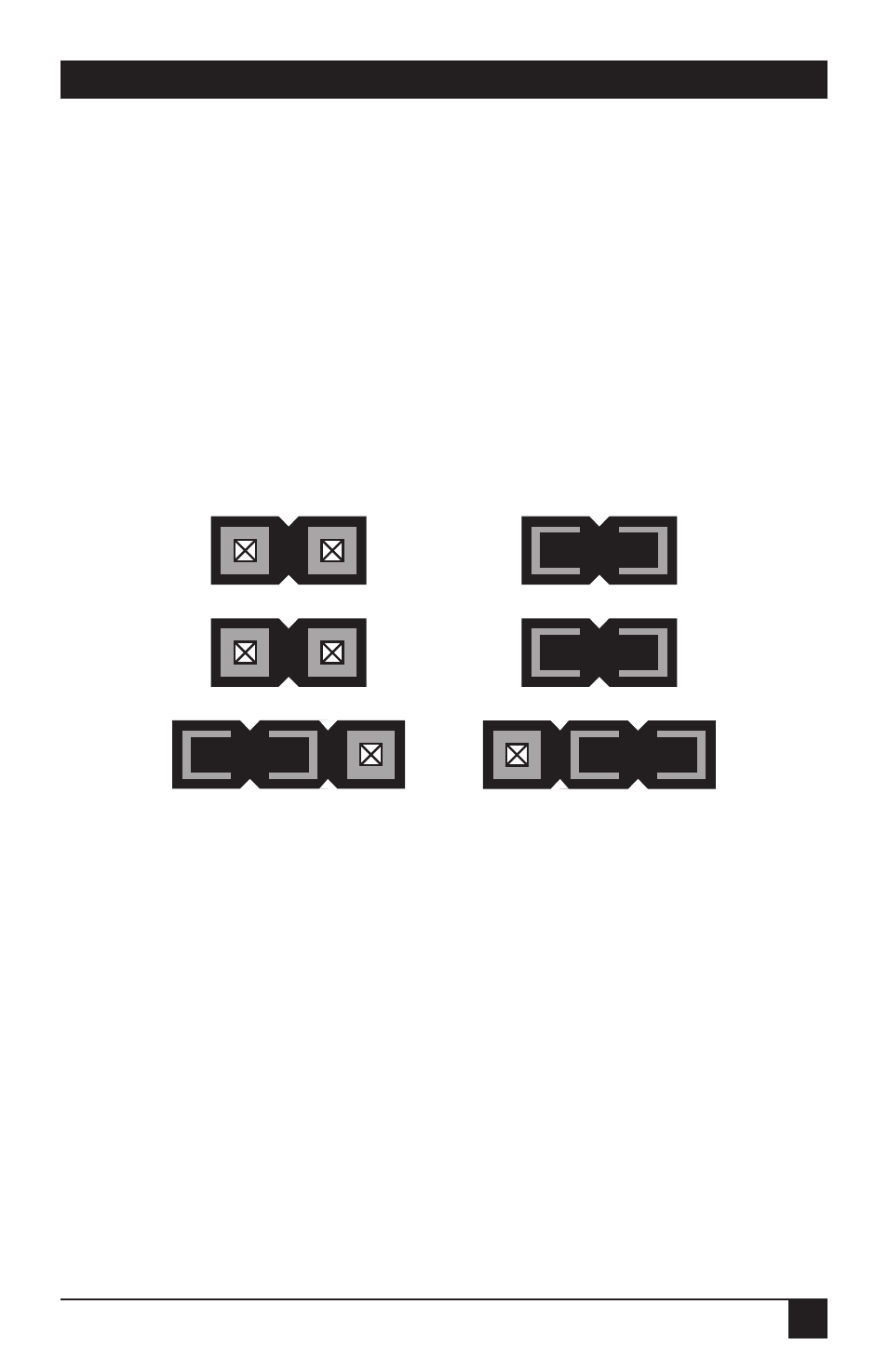
If you’ll be using a VGA monitor in your Extender system, leave these jumpers set
as they are (in their factory-default positions). But if you need to use an RGB
monitor instead, take these steps (refer to Figure 3-2):
• Install a jumper on JP6 if you want the Extender to add the HSYNC
(horizontal sync) polarity signal to the red color signal.
• Install a jumper on JP10 if you want the Extender to add the VSYNC (vertical
sync) polarity signal to the red color signal.
• JP11 is the main VGA vs. RGB control. To select RGB on the local side (if your
computer is transmitting RGB video), move the jumper from the left-hand
posts to the right-hand posts, as shown below.
Figure 3-2. Setting the VGA/RGB jumpers.
Installed
Removed
Removed
Installed
Jumper on right-
hand posts
Jumper on left-
hand posts
JP6
JP10
JP11
VGA Signals
(Factory Defaults)
RGB Signals