Aries Automotive 203040-2 User Manual
Page 2
Page 2 of 4
Once the top of the Bracket is properly lined up in the T-Slot, rotate the bottom of the Bracket into
position with the holes in the pinch weld. Secure the 12mm threaded end of the Nut and Bolt Plate with
(1) 12mm Flat Washer, (1) 12mm Lock Washer and (1) 12mm Hex Nut. Rotate the Nut and Bolt Plate
around to line up the Nut with the remaining hole and thread (1) 10mm x 35mm Hex Bolt, (1) 10mm Flat
Washer and (1) 10mm Lock Washer into the Nut, (Figure 4). Do not tighten at this time.
5. Align the holes in the pinch weld with the holes in the front Mounting Bracket. Insert (2) 8mm x 30mm
Hex Bolts with (2) 8mm x 22mm OD x 1.5mm Large Flat Washers up from below and secure with (2)
8mm x 17.1mm OD x 1.3mm Small Flat Washers, (to clear the bracket), (2) 8mm Lock Washers and (2)
8mm Hex Nuts, (Figure 5). Do not tighten at this time.
6. Moving to the driver side rear, remove the tape covering the holes on the inner body panel.
a. REGULAR
CAB: Select (1) 12mm Bolt Plate and thread (1) 11mm Plastic Retainer part way
onto it. Insert the Bolt Plate and Retainer into the rear mounting hole, (Figure 6).
IMPORTANT: The Plastic Retainer is designed to prevent the Bolt Plate from falling into the
body cavity and to aid in mounting the Bracket. Once inserted, thread the Plastic Retainer all of
the way down to snug up against the body.
7. Hang the driver side Rear Mounting Bracket from the Bolt Plate and Retainer and secure it with the
included (1) 12mm Lock Washer, (1) 12mm Flat Washer, and (1) 12mm Hex Nut, (Figure 6&7) . Insert
(1) 10mm x 35mm Hex Bolt, (1) 10mm Flat Washer with (1) 9mm Plastic Retainer into the hole at the
rear of the Mounting Bracket from the outside-in, (Figure 8). NOTE: The Plastic Retainer is intended to
protect the outer painted surface of the body. Thread the Plastic Retainer onto the Hex Bolt so that it is
between the 10mm Flat Washer and the body. Secure the Bracket with (1) 10mm Lock Washer, (1)
10mm Flat Washer and (1) 10mm Hex Nut. Do not tighten hardware at this time.
8. Attach the Sidebar to the Mounting Brackets using the included (2) 1/2” x 2” Hex Head Bolts, (2) 1/2”
Flat Washers, and (2) 1/2” Lock Washers. Do not tighten hardware at this time.
9. Align the Sidebar and adjust as required. Once properly aligned, tighten all hardware.
10. Repeat steps 2-9 for passenger Sidebar installation. NOTE: For passenger side installation, replace the
ground strap next to the mounting holes for the front Mounting Bracket removed in Step 3.
11. Do periodic inspections to the installation to make sure that all hardware is secure and tight.
To protect your investment, wax this product after installing. Regular waxing is recommended to add a
protective layer over the finish. Do not use any type of polish or wax that may contain abrasives that could
damage the finish.
For stainless steel: Aluminum polish may be used to polish small scratches and scuffs on the finish. Mild
soap may be used also to clean the Sidebar.
For gloss black finishes: Mild soap may be used to clean the Sidebar.
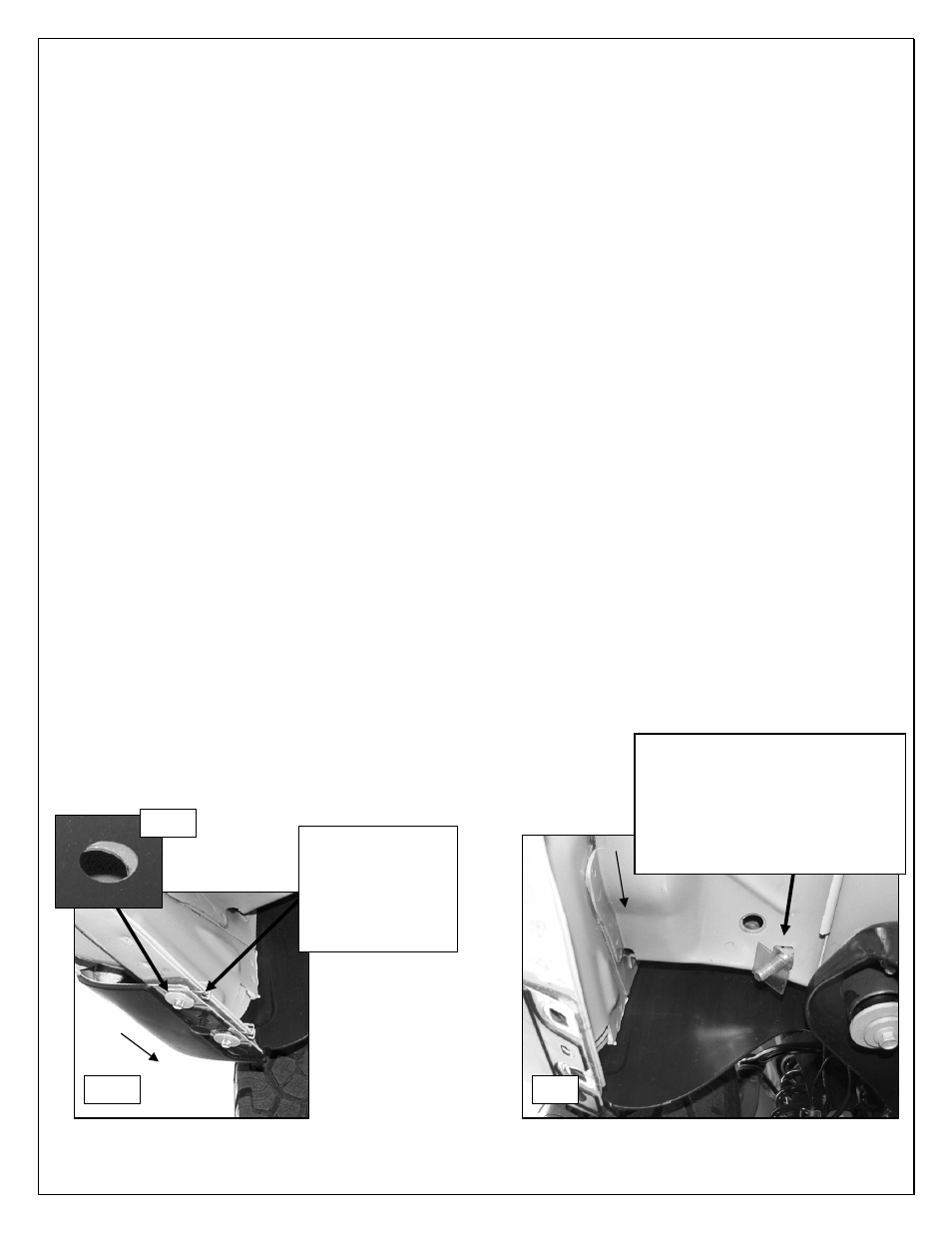
Driver Side Installation Pictured
Driver Side Installation Pictured
Remove these two
hex bolts, metal clips
and the plastic pin.
Drill a 3/8" hole
through the pinch
weld to clearance
holes if necessary
Fig 2
Fig 1A
Fig 1B
Front
Front
Insert the Nut and Bolt Plate into this
square hole and line up the nut with
the round hole. Thread the plastic
retainer only part way down the
threaded end of the bolt.
On passenger side installation,
remove the ground strap for access.
Replace after Bracket installation