Danger – Snorkel TB47J CE User Manual
Page 36
Chapter 7 – Prestart Inspection
32
TB47J – 0075239EE
8. Test the operation of each control in both directions
from the upper controls.
9. The drive range switch and maximum travel speeds
are interlocked through a limit switch on the turn-
table that senses the main boom position. When the
main boom is raised to just below horizontal the ma-
chine should travel in low speed only. To operate in
high speed the booms must be stowed.
Emergency Stop
Push the emergency stop button in to turn off the engine.
The upper control functions should not operate with the
emergency stop in this position.
Emergency Power
Pull the emergency stop button up and place the anti-
restart master switch in the on position.
Hold the engine/emergency power switch in the emer-
gency power position and step on the platform foot switch
to operate the aerial platform from the upper controls us-
ing the emergency power system.
Horn
Press the horn button to ensure that it sounds to warn
personnel in the area.
Electrical Power Outlet
With the engine running, place the machine/generator
control (refer to Figure 7.20) in the generator position to
provide electrical power to the outlet at the platform and
to the outlet on the end of the generator housing.
Figure 7.20 – Upper Control Panel Front
Plug an electrical tool into the receptacle at the platform
and at the generator and try to operate the tool to verify
proper operation of the outlet.
Drive Motion Alarm
The machine may be equipped with an optional drive
motion alarm. Drive in both the forward and reverse direc-
tions to ensure that the alarm sounds to warn personnel
in the area that the aerial platform is in motion.
Lanyard Anchors
There are two lanyard anchors below the upper control
panel (refer to Figure 7.18).
Visually inspect the lanyard anchors to make sure they
are in place, are not deformed and are securely fastened
to the platform.
Operating Controls
Use the following procedure to operate the machine from
the upper controls.
1. Turn the battery disconnect switch on.
2. At the lower controls, pull the emergency stop but-
ton outward. Insert the key in the control selector
and turn the switch to the upper control position.
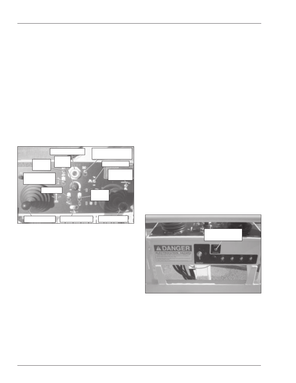
3. At the upper controls (refer to Figure 7.19), pull the
emergency stop button outward.
Figure 7.19 – Upper Control Panel Top
4. Turn the master start switch on the front of the upper
control panel to start until the engine starts, then
release it.
5. Let the engine warm to operating temperature.
A
Danger
Pinch points may exist between moving compo-
nents. Death or serious injury will result from be-
coming trapped between components, buildings,
structures, or other obstacles. Make sure all person-
nel stand clear of the aerial platform while perform-
ing the prestart inspection.
6. Place the drive/boom selector switch in the boom
position.
7. Test the platform foot switch by moving a boom func-
tion switch without stepping on the foot switch. If
movement occurs the interlock is not functioning prop-
erly. Do not operate the machine until the problem is
corrected.
Engine
Throttle
Platform
Level
Engine/Emergency
Power
Boom Extend/
Retract Switch
Drive Range
Speed
Knob
Jib Switch
Emergency Stop
Boom Joystick
Platform Rotate
Drive/Boom
Selector
Drive Joystick
Machine/
Generator Switch