Snorkel S1930CE User Manual
Page 29
Chapter 8 – Prestart Inspection
S1930 – 0361518EE
25
Place the drive/lift selector switch in the drive position
and test the operation of the joystick in both directions.
The lift functions should not operate with the selector in
the drive position.
Place the drive/lift selector switch in the lift position and
test the operation of the joystick in both directions. The
drive functions should not operate with the selector in the
lift position.
Emergency Stop
Push the emergency stop button in to turn off the electri-
cal power. The upper control functions should not oper-
ate with the emergency stop in this position.
Horn
Press the horn button to ensure that it operates properly.
Lowering Alarm and Interrupt
Raise the platform approximately 3 m (10
′). Push the
joystick forward to lower the platform. The platform should
stop lowering when it reaches about 1.5 m (5
′). Center
the joystick in neutral to reset the lowering function. Wait
for 5 seconds and then push the joystick forward to con-
tinue lowering.
Drive Motion Alarm
Drive in both the forward and reverse directions to ensure
that the alarm sounds to warn personnel in the area that
the aerial platform is in motion.
Flashing Light
If the machine is equipped with the optional flashing light,
visually check to see that it flashes. The light should
flash when power is turned on to operate the machine.
Battery Condition Indicator
The optional battery condition indicator (refer to Figure
8.21) is located on the upper control panel. With the ma-
chine set up for upper control operation, check to see
that the gauge displays a power reading.
Figure 8.21 – Upper Controls
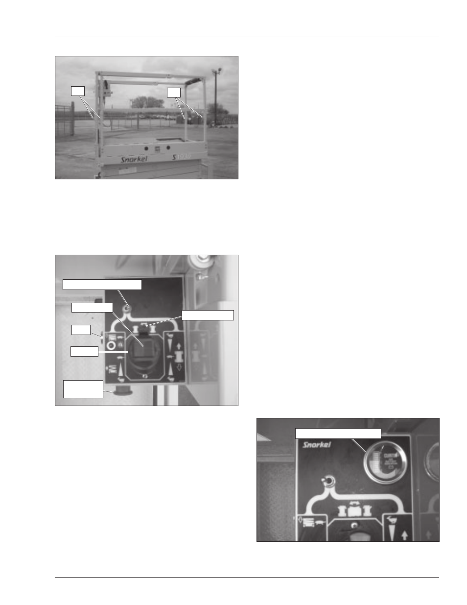
Figure 8.19 – Swing-Down Rails Pin Location
The pins must securely fasten the swing-down rails in
the upright position.
Operating Controls
With the aerial platform stowed, test the operation of each
control from the upper control station (refer to Figure 8.20).
Figure 8.20 – Upper Controls
Place the battery disconnect switch in the on position
and from the lower controls, place the control selector in
the upper controls position. Pull the emergency stop but-
ton outward to turn on the electrical power to the upper
controls.
From the upper controls, test the interlock by moving the
joystick without engaging the interlock switch. If move-
ment occurs the interlock is not functioning properly. Do
not operate the machine until the problem is corrected.
Pin
Pin
Horn
Steer Switch
Joystick
Emergency
Stop Button
Interlock Switch
Drive/Lift Selector Switch
Battery Condition Indicator