Raising and lowering 9-3, Extending 9-3, Brakes 9-3 – Snorkel S1930 User Manual
Page 37: Swing-out trays 9-3, Brake disc, 9-3, Brake pin, 9-3, Disengaging, 9-3, Swing-out tray, 9-3, Extend handle, 9-3, Raising and lowering, 9-3
Raising and Lowering
The raise speed is proportional to the joystick position.
The farther the joystick is moved, the faster the platform
raises. There is only one lowering speed.
1. Place the drive/lift selector switch (refer to Figure
9.2) in the lift position.
2. Squeeze and hold the interlock switch against the
joystick.
●
To raise the platform, slowly pull the joystick back
until the desired speed is reached.
●
To lower the platform, slowly push the joystick
forward.
Extending
The platform can be extended and securely locked into
seven different positions. Use the following procedure to
extend or retract the platform.
1. Stand on the non-extendible part of the platform
floor, facing the front of the platform.
2. Remove the snapper pin and push on the handles
(refer to Figure 9.3) to extend the deck.
Figure 9.3—Platform Extend Handle
3. Replace the snapper pin when the platform is ex-
tended.
4. Try to move the rails back and forth to make sure the
platform extension deck is locked in position.
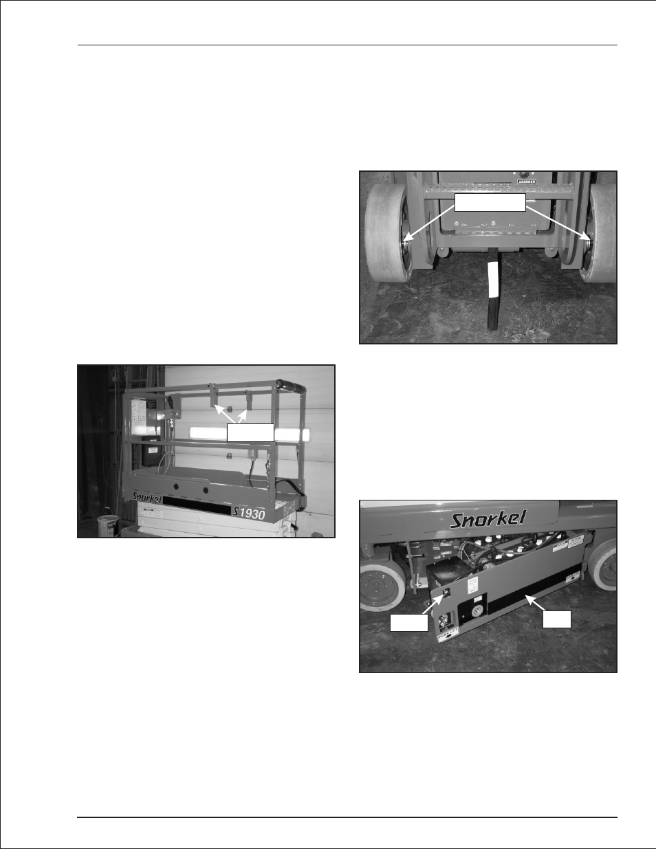
Brakes
Each rear wheel is equipped with a mechanical
spring-applied, hydraulically released parking brake.
When the drive control is in neutral, a spring-activated
pin (refer to Figure 9.4) protrudes through an opening in
the brake disc to prevent movement. A flow control valve
slows the pin movement to allow the aerial platform to
stop before the parking brakes engage.
Figure 9.4—Mechanical Brake
This system operates automatically to stop and hold the
aerial platform when the drive controls are released or
power is interrupted. Manually disengage the brakes be-
fore towing or winching the aerial platform as described
under Towing in Chapter 11—Emergency Operation.
Swing-Out Trays
Batteries and hydraulic components are enclosed in
swing-out trays (refer to Figure 9.5) on each side of the
c h a s s i s.
Figure 9.5—Swing-Out Tray
The tray on the right side of the chassis contains the
lower controls, the hydraulic directional control valve,
the pump, free-wheeling valve, and the hydraulic fluid
filter. The tray on the left side contains the four batteries
and the battery charger.
S1930 – 0361266
9 - 3
Chapter 9. Operation
Latch
Tray
Handles
Brake Pins