Boom operation, Driving and steering, Danger – Snorkel SB85J-sn10000+ User Manual
Page 13: Warning
Operation
SB85J Fixed Axle – 0112998
11
8. Let the engine warm to operating temperature.
Boom Operation
Use the following procedure to operate the turntable,
boom, or platform functions.
1. Step down on the platform foot switch. This switch
must be held down to operate the upper controls.
2. Hold the appropriate control in the desired direction.
Always look in the direction of movement.
3. Releasing the control to its neutral position, or releas-
ing the foot switch will stop movement.
Driving and Steering
A
Danger
The aerial platform can tip over if it becomes unstable.
Death or serious injury will result from a tip-over ac-
cident. Do not drive an elevated aerial platform on
soft, uneven, or sloping surfaces. Do not drive the
machine on grades that exceed 30 percent.
For operation on grades up to 30 percent, it is recom-
mended that the main boom be near horizontal and the
jib elevated just enough to provide adequate ground
clearance. A 30 percent grade is a 0.91 m (36″) vertical
rise in 3.05 m (10′) horizontal length.
Avoid driving with the platform over the front (steer) end
of the chassis. In this position the machine is difficult to
control because:
drive and steer control movements and their resulting
machine movements are reversed.
when driving fast, sudden turns or stops produce more
severe reactions to platform occupants.
more turning space is required to prevent the platform
from colliding with obstacles several feet beyond the
path of the tires.
A
Warning
Death or serious injury can result from improperly
driving or steering the aerial platform. Read and un-
derstand the information in this manual and on the
placards and decals on the machine before operating
the aerial platform on the job.
The blue and yellow arrows on the chassis indicate the
direction the chassis will move when the drive or steer
control is moved toward the corresponding color.
When the machine is in the stowed position, with the
booms centered between the rear wheels, the direction
of drive and steer control movement corresponds with
the direction of chassis movement.
•
•
•
When the turntable is rotated from the stowed position,
with the booms to either side of or in front of the chassis,
the direction of control movement does not correspond
with the direction of chassis movement.
To avoid confusion, always drive to the work area or
move between work areas with the turntable and booms
in the stowed position. After arriving at the work area, the
booms may be positioned to the side or the front of the
chassis for final positioning. Always look in the direction
of movement as indicated by the directional arrows on
the chassis.
Use the following procedure to operate the drive and
steer functions:
1. Determine the desired drive range for the specific
driving conditions.
Place the switch in the appro-
priate position to achieve the desired drive wheel
operation.
Use high range (two wheel drive) when traveling
across firm, flat, level surfaces. High range can only
be activated when the booms are stowed. High
range is for high speed, low torque operation.
Use mid range (four wheel drive) when traveling
across soft surfaces or those with small inclines.
Mid range can only be activated when the booms
are stowed. Mid range is for medium speed, high
torque operation.
Use low range (four wheel drive) for driving on load-
ing ramps or other steep grades and when safety
considerations demand slow deliberate machine
movement. Low range is for low speed, high torque
operation.
2. Determine the desired steer mode for the specific
driving conditions. Place the switch in the four wheel
coordinated, two wheel, or crab steer mode position
to achieve the desired machine movement.
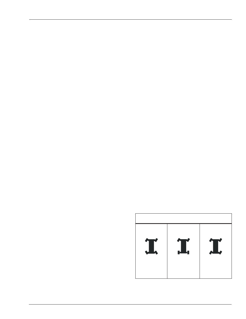
Steer Modes
Crab
• Front and rear
wheels turn in
steer direction
Four Wheel
Coordinated
• Front wheels turn
in steer direction
• Rear wheels turn
in the opposite
direction
Two Wheel
• Front wheels turn
in steer direction
• Rear wheels do
not turn
Use two wheel steer for most machine operation
such as travel between jobs and to position the
machine near the job location.
•
•
•
•
Figure 6 – Steer Modes