Micropump GM Series Service Instructions User Manual
Page 6
MICROPUMP, INC.
A Unit of IDEX Corporation
PO Box 8975, Vancouver, WA 98668-8975 • Phone: 360/253-2008 • Fax: 360/253-8294
MICROPUMP
LIMITED
A Subsidiary of Micropump, Inc.
Howard Road, Eaton Socon, St.
Neots, Cambridgeshire, PE 19 8ET England, • Phone: (44) (0) 1480-356600• Fax: (44) (0) 1480-35630
0
REVISION
LTR.
DESCRIPTION
DATE
BY
A
ORIGINATED PER E14164
1/28/04
CMA
PART NUMBER:
L23154
Page 6 of 9
6.5 Bushing Installation
6.5.1 Remove all bushings (3) from bearing plate (2) and pump body (10) using
a tap and handle. Thread tap into bushing approximately ½” (12 mm) and pull
bushings out.
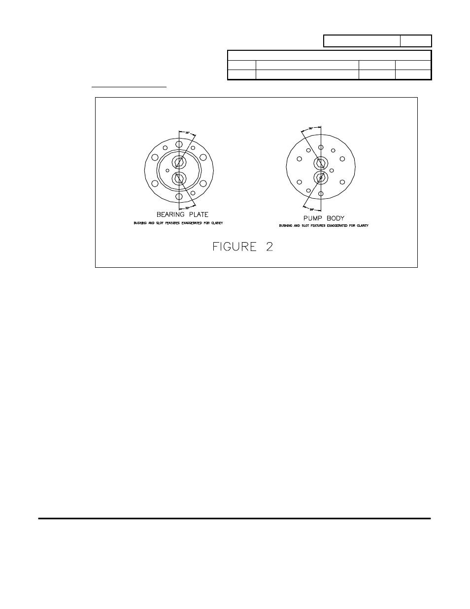
6.5.2 Install 4 bushings into bearing plate (2) 0.010” to 0.020” (0.26 mm to 0.51
below bearing plate sealing surface, with the slots (if present) aligned as shown in
figure 2. Use a bushing insertion tool and hand press or non-rotating drill press.
6.5.3 Install the first 4 bushings into pump body (10) 0.010” to 0.020” (0.26 mm
to 0.51 mm) below sealing surface of the “gear end” of the pump body. Align the
bushings slots as in figure 2. Install the remaining bushing into pump body from
driven magnet (12) end, aligning the slots as in figure 2, and the bushing flush with
the pump body surface.
6.5.4 Check all bushings for proper installation depth. Check bushings after
installation with a new gear shaft to insure that clearance between shafts
and bushings is at least a sliding fit.
6.5.5 If bushings are tight on shafts, very carefully hand ream bushings after
installation using a 0.251” (6.4 mm) diameter reamer. This should be
done as straight as possible to obtain maximum perpendicularity. Do not
force reamer into bushings, and do not ream bushings unless necessary.