Programming, Installing and mounting, Testing the detector – 2GIG CO3-345 Carbon Monoxide Detector User Manual
Page 2: Proper carbon monoxide detection location
2
©2013 2GIG by Linear Corporation. All Rights Reserved.
PROGRAMMING
The following steps are guidelines for programming (learning) the Wireless Carbon
Monoxide Alarm (2GIG‐CO3‐345) into the 2GIG Control Panel. Scroll between
op ons using the ← and → arrows. Move to the previous or next prompt by
pressing the ↑ and ↓ arrows.
1
Select RF sensor #(01 to 48). Assign the Wireless Carbon Monoxide Alarm to a
new zone.
2
Select RF sensor type.
(14) 24‐hour Carbon Monoxide Alarm
3
Select RF equipment type.
4
Select RF sensor equipment code. Enter 0859 (in Canada) or 0860 (in U.S.A.) for
the 2GIG‐CO3‐345 Alarm.
5
Enter RF sensor serial number (7 digits).
Manual Entry: Type in the last 7 digits of the TX ID that is found outside the box
or on the
bottom of the head unit by removing the base.
Auto Entry: With the panel in Learn‐in mode (press Shift then Learn) cause a
tamper on the alarm by twisting the base unit counter‐clockwise and removing
it. The correct TX ID should appear. Accept the correct TX ID by pressing ok.
Remember to press the ↓ arrow to continue through the system configuration
prompts.
6
Select RF sensor equipment age.
(0) new (product is new)
(1) existing (product already exists)
7
Select RF sensor loop number (1).
8
Select RF sensor 1 dialer delay.
(0) disabled (there should never be a dialer delay on this type of alarm)
9
Construct RF sensor descriptor. Press Insert then press any number between
002 and 255 to add a word. For example, if you wanted to name this alarm as
“Carbon Monoxide Alarm,” press Insert then press 032 for CARBON
MONOXIDE. Press Insert then press 005 for ALARM.
10
Select RF sensor reports (0 to 1).
(1) enabled (sensor reports to the central station)
11
Select RF sensor supervised (0 to 1).
(1) enabled (sensor reports loss of supervision or low battery)
12
Select RF sensor chime (0 to 13).
(0) disabled (panel will not chime when sensor is activated)
13
To program another sensor, click next.
14
To exit programming, click skip then end and exit. Upon exit, the panel takes a
few seconds to reset.
Installing and Mounting
Determine the best location for the detector, one that provides proper carbon
monoxide detection.
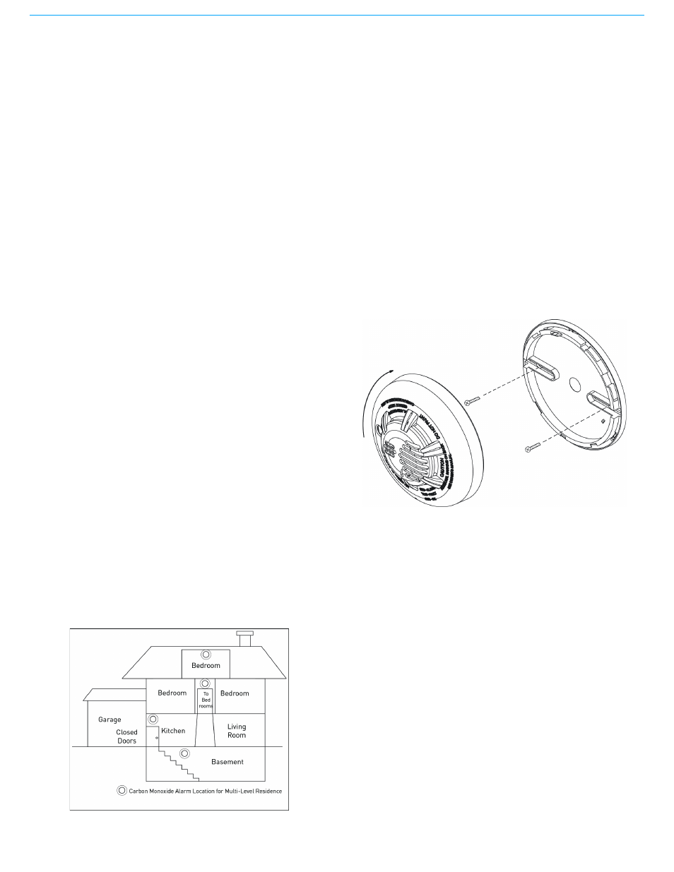
Proper Carbon Monoxide Detection Location
Wall‐mounted detectors should be positioned at least as high as a light switch, and
at least six inches (15cm) from the ceiling. In a ceiling location, the detector should
be at least 12 inches (30cm) from any wall.
Ideal Locations:
•
Within 10 feet (3m) of a sleeping area
•
Inside the bedroom if it contains a fuel burning appliance
•
On every floor of the building
•
Ideally, install in any room that contains a fuel burning appliance
•
If the appliance or the room is not normally used, such as the boiler room, the
detector should be placed just outside the room so the alarm can be heard
more easily
This Wireless Carbon Monoxide Alarm should only be commissioned
and installed by a competent engineer.
NOT Ideal Locations:
•
Directly above a sink, cooker, stove or oven
•
Do not locate detector within 5 feet (1.5m) of any cooking appliance
•
Next to a door or window that would be affected by drafts,. extractor fan or air
vent
•
Outside
•
Do not install in any environment that does not comply with the detector’s
environmental specifications
•
In or below a cupboard
•
Where air flow would be obstructed by curtains or furniture
•
Where dirt or dust could collect and block the sensor
•
Where it could be knocked, damaged, or inadvertently removed
To Mount the Detector
1
See the figure below and install the mounting base on the ceiling or on the wall
(if local ordinances permit) using screw locations as required. Use the two
screws and anchors provided. Maneuver the base so the screws are at the
elbow of the screw slots and secure.
2
Fit the detector inside the base by aligning it over the base as shown
(detector’s alignment notch should be slightly offset from mounting base
tamper release tab).
3
Test the detector after completing the installation (see Testing the Detector).
See the 2GIG Security System Install Guide for additional information
concerning the use of wireless devices.
WARNING:
DO NOT attach the detector to removable ceiling panels.
4
Two warning labels are provided in the detector box. Place one next to the CO
detector and another near to a source of fresh air where members of the
household will gather if alarm signal sounds.
WARNING:
Airborne dust particles can enter the detector. 2GIG Technologies
recommends the removal of detectors before beginning construction or
any other dust producing activity. Carbon monoxide detectors are not to
be used with detector guards unless the combination has been evaluated
and found suitable for that purpose.
Tamper Protection
A tamper alert is displayed at the Control Panel if the built‐in tamper switch is
removed from its mounting base. The Wireless Carbon Monoxide Alarm includes a
tamper resistant feature that prevents removal from the mounting base without the
use of a tool. To engage the tamper resistant feature, cut the small plastic tab
located on the mounting base and then install the detector.
To remove the detector from the base once it has been made tamper resistant, use
appropriate screwdriver to depress the square tamper release tab located on the
skirt of the mounting base and turn the detector counterclockwise.
Testing the Detector
Before testing, notify the central monitoring station that the security system is
undergoing tests and maintenance. This action prevents unwanted alarms.
Testing the detector activates an alarm and sends an alarm signal to the Control
Panel. Also, the test function cannot be used if the detector has a trouble or end‐of‐
life condition.
Detectors must be tested after installation and following periodic maintenance.
To Test Detector Operation
To test the detector’s sounder, LEDs, and transmitter, do the following:
1
The test button is located on the detector housing.
2
Push and hold the test button for a minimum of 5 seconds. The Control Panel
will trigger and the detector will go into alarm. The sounder begins the
temporal 4 pattern and the red LED blinks. The security system’s Control Panel
displays the detector’s name in alarm.