Inserting and replacing batteries, Fcc and industry canada regulatory information, Specifications – 2GIG DW20R-345 Recessed DW Contact User Manual
Page 2: Warning
It is important to select the proper placement of the recessed sensor/transmitter and magnet. The DW20R Sensor
comes with two different tops, however, the screw mount is recommended for securing the sensor to a door frame. The
magnet does not have a second top with a flange to screw it into place so you must be extremely careful to ensure that
the magnet is tightly in place upon installation. To mount, do the following:
1
Mark the location on the door or window frame for the sensor/transmitter and magnet to be installed (use a
marker or pencil). Ensure that the two holes you intend to drill are lined up directly across from each other (see
figure on previous page).
2
Using an 11/16" drill bit, slowly drill the first hole for the transmitter. The DW20R Sensor is specifically designed to
be slightly larger than an 11/16" hole. Drill carefully by slowly routing the hole little by little to ensure a snug fit.
Use the flanged cap with the included screws to mount the transmitter to the door or window frame.
3
Drill a matching hole for the magnet, directly opposite from the transmitter, also using an 11/16" drill bit.
Inserting and Replacing Batteries
If a supervised sensor battery is low, a low battery notification is indicated on the Control Panel. When the 2GIG system
indicates that the sensor has a low battery, replace the battery immediately. Use only the recommended replacement
batteries (See Specifications). To install or replace the battery, do the following:
1
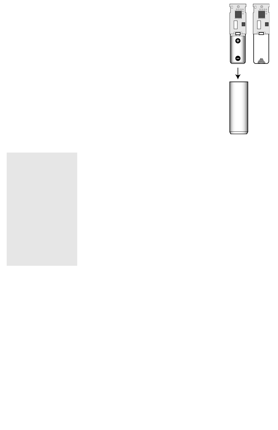
To remove the sensor top, use a small flat‐head screw driver to pry open the top.
2
To get to the battery, you must remove the circuit board. Notice that the circuit board fits inside a channel inside
of the case. After replacing the battery, reinsert the circuit board to fit snugly inside the channel of the case.
3
Observe polarity as shown in the figure! Verify programming and RF communication with the Control Panel.
WARNING:
The polarity of the battery must be observed, as shown. Improper handling of lithium batteries may
result in heat generation, explosion or fire, resulting in personal injuries. Replace only with the same or equivalent
type of battery as recommended by the manufacturer (see Specifications). Batteries must not be recharged,
disassembled or disposed of in fire. Disposal of used batteries must be made in accordance with the waste
recovery and recycling regulations in your area. Keep Away From Small Children. If batteries are swallowed,
promptly seek medical attention.
California Only: This Perchlorate warning applies only to Manganese Dioxide Lithium cells sold or distributed ONLY in /
California, U.S.A. Perchlorate Material‐special handling may apply. See dtsc.ca.gov/hazardouswaste/perchlorate.
Specifications
FCC and Industry Canada Regulatory information
This device complies with Part 15 of the FCC's Rules. Operation is subject to the following two conditions:
1) This device may not cause harmful interference, and
2) This device must accept any interference received, including interference that may cause undesired operation.
This equipment has been tested and found to comply with the limits for a Class B digital device, pursuant to Part 15 of the FCC Rules. These
limits are designed to provide reasonable protection against harmful interference in a residential installation. This equipment generates, uses
and can radiate radio frequency energy and, if not installed and used in accordance with the instructions, may cause harmful interference to
radio communications. However, there is no guarantee that interference will not occur in a particular installation. If this equipment does cause
harmful interference to radio or television reception, which can be determined by turning the equipment off and on, the user is encouraged to
try to correct the interference by one or more of the following measures:
•
Reorient or relocate the receiving antenna.
•
Increase the separation between the equipment and receiver.
•
Connect the equipment into an outlet on a circuit different from that to which the receiver is connected.
•
Consult the dealer or an experienced radio/TV technician for help.
This product complies with FCC radiation exposure limits for an uncontrolled environment. Avoid operating this product at a distance less than
20 cm from the user.
Caution: Any changed or modifications not expressly approved by the party responsible for compliance could void the user's authority to
operate this equipment.
LIMITED WARRANTY
This 2GIG Technologies product is warranted against defects in material and workmanship for 2 years. This warranty extends only to wholesale
customers who buy direct from 2GIG Technologies or through 2GIG Technologies’ normal distribution channels. 2GIG Technologies does not
warrant this product to consumers. Consumers should inquire from their selling dealer as to the nature of the dealer’s warranty, if any.
There are no obligations or liabilities on the part of 2GIG Technologies for consequential damages arising out of or in connection with use or
performance of this product or other indirect damages with respect to loss of property, revenue, or profit, or cost of removal, installation, or
reinstallation. All implied warranties for functionality, are valid only until the warranty expires. This 2GIG Technologies Warranty is in lieu of all
other warranties expressed or implied.
For technical support in the USA and Canada:
855-2GIG-TECH (855-244-4832)
For technical support outside of the USA and Canada:
Contact your regional distributor
Visit dealer.2gig.com for a list of distributors in your region.
PN: IPM-1054-01 Rev. C
2GIG Copyright © 2013. All rights reserved.
Wireless Signal Range
450 ft, open air, with 2GIG Wireless Control Panel
Code Outputs
Alarm; Alarm Restore; Supervisory; Low Battery
Transmitter Frequency
345.000 MHz (crystal controlled)
Transmitter Frequency Tolerance
±15kHz
Transmitter Bandwidth
24kHz
Modulation Type
Amplitude Shift Keying‐On/Off Keying (ASK‐OOK)
Unique ID Codes
Over one million different code combinations
Supervisory Interval
70 minutes
Peak Field Strength
Typical 50,000 uV/m at 3m
External Input Sampling Current
20 uA
External Input
Accepts N/C dry contact devices
Reed Switch Magnetic Sensitivity
10 to 20 amp turns
Reed Sensitivity
0.625 in. (1.59 cm) minimum gap, 0.85 in. (2.16 cm) typical
Magnet Dimensions (HxD)
0.5 x 0.75 in. (1.27 x 1.9 cm) typical
Magnet Type
Rare earth
Sensor Dimensions (HxD)
2.57 x 0.75 in. (6.53 x 1.9 cm)
Weight (including battery and magnet)
1.25 oz. (35.4 g)
Housing Material
ABS plastic
Color
White
Operating Temperature Limits
32° to 120° F (0° to 49° C)
Relative Humidity
5‐95% Non‐Condensing
Battery (installed with pull tab)
One Panasonic CR2 or equivalent Lithium battery
Included Accessories
Two magnet cap styles (Normal and Screw type) Two Phillip’s flat‐head screws